Basic Operation
6.1.2 Frequency Reference Settings: b1-01, H3-01, H3-08, H3-09
6-6
J
Function and Signal Level for Multi-function Analog Input (Terminal 16):
H3-04, H3-05
D
This function is useful when switching between two analog inputs. The input is from terminal 16.
D
When using the multi-function input (terminal 16) as the frequency reference terminal, first set the
multi-function analog input function to “Auxiliary Reference” by setting constant H3-05 to 0.
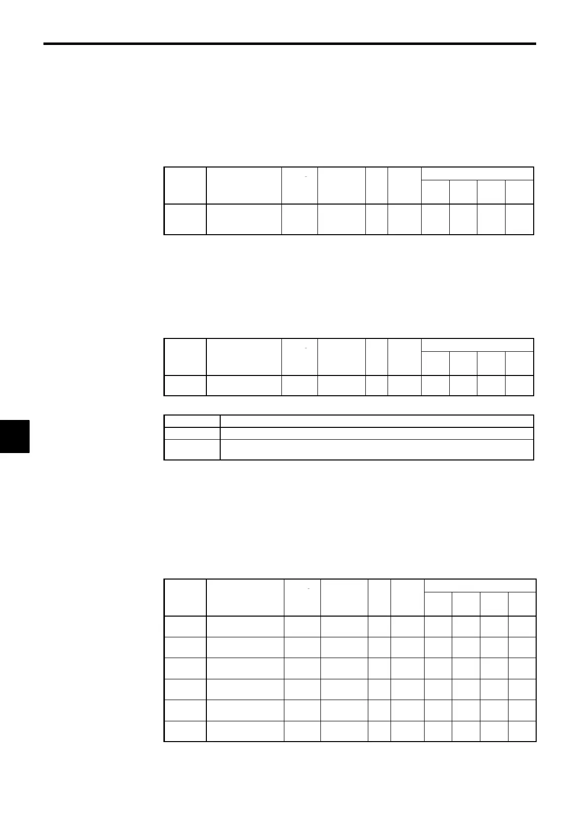
Function for Multi-function Analog Input, Terminal 16: H3-05
User
Change
Valid Access Levels
Constant
Number
Name
during
Opera-
tion
Setting
Range
Unit
Factory
Setting
V/f
Control
V/f with
PG
Open
Loop
Vector
Flux
Vector
H3-05
Multi-function ana-
log input (terminal
16)
×
0to1F − 0
B B B B
D
The auxiliary reference is factory-preset to 0.
D
After setting H3-05 to 0, set any one of the multi-function inputs (H1-01 through H1-06) to a value
of 3 (multi-step speed reference 1).
D
When a multi-function analog input has been set to “Auxiliary Reference,” it is treated as frequency
reference 2 during multi-step speed operation, so it can’t be used unless the multi-step speed reference
1 has been set.
Signal Level for Multi-function Analog Input, Terminal 16: H3-04
D
Set the signal level for the multi-function analog input.
User
Change
Valid Access Levels
Constant
Number
Name
during
Opera-
tion
Setting
Range
Unit
Factory
Setting
V/f
Control
V/f with
PG
Open
Loop
Vector
Flux
Vector
H3-04
Signal level selec-
tion (terminal 16)
×
0, 1 − 0
B B B B
D
Settings
Setting Function
0
0 to 10 VDC input [11-bit + polarity (positive/ negative) input]
1
−10 to 10 VDC input
(A negative voltage is a reference for reverse rotation.)
J
Adjusting Analog Inputs: H3-02, H3-03, H3-06, H3-07, H3-10, H3-11, H3-12
D
There are three constants used to adjust the analog inputs: The gain, bias (both set separately for each
input), and filter time constant (a single value for all of the inputs).
• The gain and bias can be adjusted separately for each analog input (terminals 13, 14, and 16).
Gain: Set the frequency corresponding to a 10 V (20 mA) input as a percentage of the
maximum frequency. (The maximum output frequency set in E1-04 is 100%.)
Bias: Set the frequency corresponding to a 0 V (4 mA) input as a percentage of the
maximum frequency. (The maximum output frequency set in E1-04 is 100%.)
• Set the gains and biases for terminals 13, 14, and 16 as follows:
User
Change
Valid Access Levels
Constant
Number
Name
during
Opera-
tion
Setting
Range
Unit
Factory
Setting
V/f
Control
V/f with
PG
Open
Loop
Vector
Flux
Vector
H3-02
Gain for terminal 13
f
0.0 to
1000.0
% 100.0
B B B B
H3-03
Bias for terminal 13
f
−100.0 to
100.0
% 0.0
B B B B
H3-10
Gain for terminal 14
f
0.0 to
1000.0
% 100.0
A A A A
H3-11
Bias for terminal 14
f
−100.0 to
100.0
% 0.0
A A A A
H3-06
Gain for terminal 16*
f
0.0 to
1000.0
% 100.0
B B B B
H3-07
Bias for terminal 16*
f
−100.0 to
100.0
% 0.0
B B B B
* The settings for terminal 16 are valid only when the multi-function analog input has been se-
lected. The gain and bias set here will be disregarded if a frequency reference is selected and
the values set for terminal 13 will be used.
6
 Loading...