Wiring
3-4
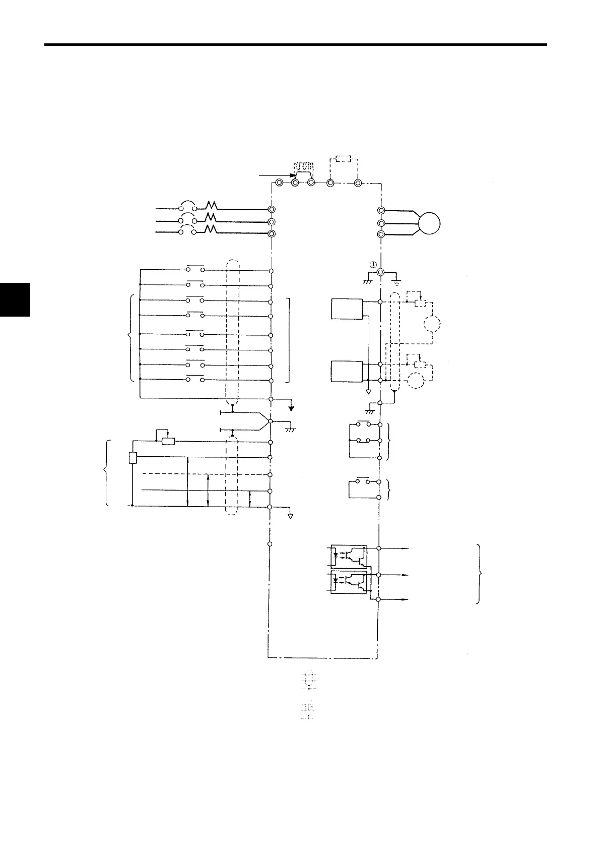
3.2 Connection Diagram
The connection diagram of the VS-616G5 is shown in Figure 3.2.
When using the Digital Operator, the motor can be operated by wiring only the main circuits.
* Shield
* Twisted-pair wires
VS-616G5
Braking Resistor Unit (Optional)
©
¨ 1 B1 B2
MCCB
3-phase power
200 to 230 V
50/60 Hz
R (L1)
S (L2)
T (L3)
Factory-
preset
functions
Forward Run/Stop
Forward run command
(forward when closed)
Reverse Run/Stop
Reverse run command
(reverse when closed)
External fault
3
Fault reset
4
Multi-step speed setting 1
(Master/auxiliary switch)
5
Multi-step speed setting 2
6
Jog frequency reference
7
External baseblock command
8
Multi-function contact
inputs
11
Sequence common
(Insulated from 0 V
terminal)
12 Shield terminal
External
frequency
references
2kΩ
15 Frequency setting power
15 V, 20 mA
2kΩ
0to10V
13 Master speed reference
−10 to 10 V (20 k Ω)
(Default: 0 to 10 V/100%)
4to20mA
P
14 Master speed reference
4 to 20 mA (250 Ω)
0to10V
P
16 Multi-function analog input
(−10 to 10 V (20 k Ω)
(Default: Auxiliary frequency
reference
0 to 10 V/100%)
0V
P
+
AM
17
0V
33
Frequency setting
power:
−15 V, 20 mA
U (T1)
V (T2)
W (T3)
Motor
IM
(Ground to 100 Ω max.)
23
+
−
Multi-function analog output
−10 to 10 V
(Default: Output current
5 V/Inverter rated current)
21
22
FM
−
Multi-function
open-collector
output
48 V , 50 mA
max.
Multi-function output
common
27
Open collector 2
(Default: Speed
agree signal)
26
Open collector 1
(Default: Zero speed
signal)
25
Multi-function contact output
250 VAC, 1Amax.
30 VDC, 1Amax.
(Default: Running signal)
10
9
20
19
Fault contact output
250 VAC, 1Amax.
30 VDC, 1Amax.
Analog
monitor 1
18
(12)
Multi-function analog output
−10 to10 V
(Default: Output frequency
0 to 10 V/100% frequency)
R
S
T
¨ 2
Analog
monitor 2
DC reactor to improve input
power factor (optional)
Short-circuit bar
:
Fig 3.2 Connection Diagram (Model CIMR-G5A27P5 Shown Above)
3
 Loading...