7-95
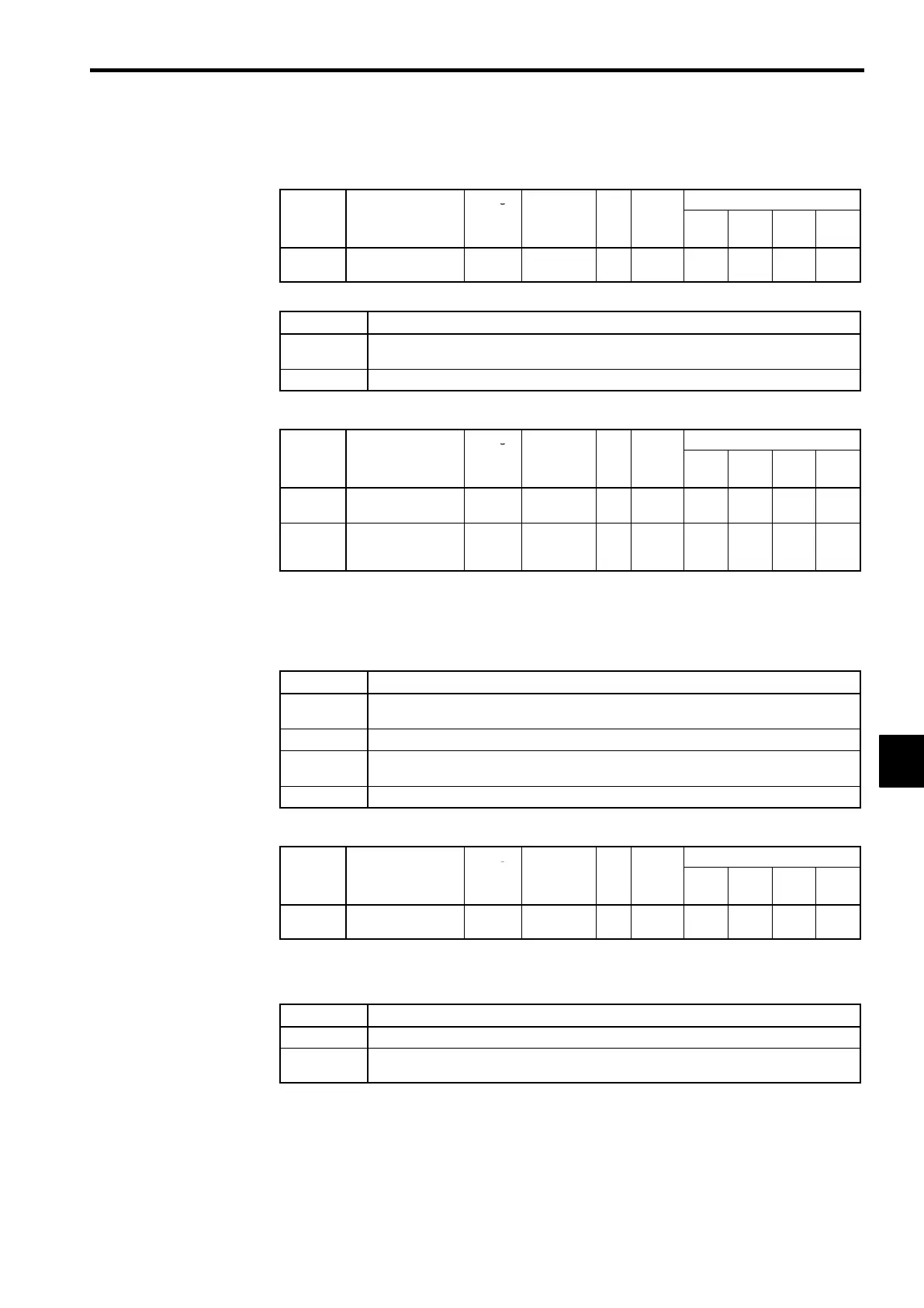
J Hardware Protection Settings: L8-01 to L8-03, L8-05, L8-07
Protection Selection for Internal DB Resistor: L8-01
User
Change
Valid Access Levels
Constant
Number
Name
during
Opera-
tion
Setting
Range
Unit
Factory
Setting
V/f
Control
V/f with
PG
Open
Loop
Vector
Flux
Vector
L8-01
Protect selection for
internal DB resistor
×
0, 1 − 0
B B B B
D
Settings
Setting Function
0
Disabled. (Select 0 when a braking resistor isn’t being used or a Braking Resistor Unit is being
used.)
1
Enabled. (Protects the braking resistor from overheating.)
Inverter Overheating (OH) Pre-alarm Settings: L8-02, L8-03
User
Change
Valid Access Levels
Constant
Number
Name
during
Opera-
tion
Setting
Range
Unit
Factory
Setting
V/f
Control
V/f with
PG
Open
Loop
Vector
Flux
Vector
L8-02
Overheat pre-alarm
level
×
50 to 110
_C
95
A A A A
L8-03
Operation selection
after overheat pre-
alarm
×
0to3 − 3
A A A A
D
Constant L8-02 specifies the detection temperature in
°
C for the Inverter overheat (OH) pre-alarm
function. An overheat pre-alarm occurs when the temperature of the cooling fins reaches this level.
D
Constant L8-03 specifies the processing that will be performed when an overheat pre-alarm occurs.
Apart from this setting, cooling fin overheating (OH1) is detected as a protection function at 105_C.
D
Settings
Setting Function
0
Decelerates to a stop in the deceleration time set in C1-09. (Protection operation: Fault contacts
operate)
1
Coast to stop. (Protection operation: Fault contacts operate)
2
Emergency stop in the emergency-stop time set in C1-09. (Protection operation: Fault contacts
operate)
3
Continues operation. (Alarm: Monitor display only.)
Input Open-phase Protection Selection: L8-05
User
Change
Valid Access Levels
Constant
Number
Name
during
Opera-
tion
Setting
Range
Unit
Factory
Setting
V/f
Control
V/f with
PG
Open
Loop
Vector
Flux
Vector
L8-05
Input open-phase
protection selection
×
0, 1 − 0
A A A A
D
This function detects changes in the main circuit DC voltage which indicate a power supply open-
phase, large imbalance in the power supply voltage, or deterioration of the main circuit capacitor.
D
Settings
Setting Function
0
Disabled.
1
Enabled. (Detects input power supply open-phase, 3-phase imbalance, or deterioration of the
main circuit capacitor.)
7
 Loading...