8.2 Programming Mode Constants
8-15
J
Carrier Frequency: C6
Con-
Name
Change
Control Methods
stant
Num-
ber
Display
Description
Setting
Range
Factory
Setting
during
Opera-
tion
V/f
V/f
with
PG
Open
Loop
Vector
Flux
Vector
Page
C6-01
Carrier Frequen-
cy Upper Limit
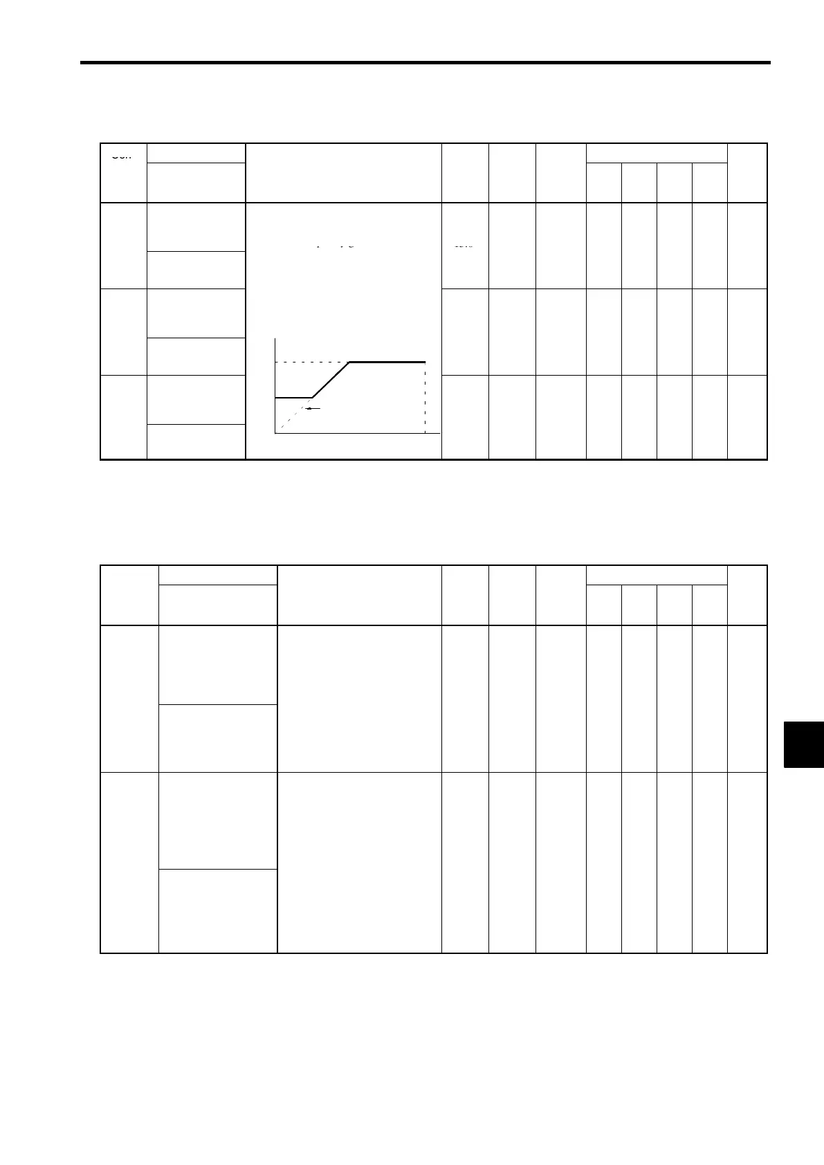
Set the carrier frequency upper limit and
lower limit in kHz units. (See note 2)
The carrier frequency gain is set as fol-
2.0 to
15.0
15.0
*
×
B B B B
7-56
Carrier Freq Max
lows:
:In vector control mode, the upper
limit of the carrier frequency is fixed
*2
*1
C6-02
Carrier Frequen-
cy Lower Limit
at C6-01
Carrier frequency
S C6-01 ≥ 10.0 : K = 3
S 10.0 > C6-01 ≥ 5.0 : K = 2
0.4 to
15.0
*
×
A A
× ×
7-56
Carrier Freq Min
C6-01
.
-
.
S 5.0 > C6-01 : K = 1
15.0
*1
C6-03
Carrier Frequen-
cy Gain
C6-02
Output frequency ×
(C6-03) × K
Output
00 to 99 00
×
A A
× ×
7-56
Carrier Gain
-
frequency
E1-04
(Max. output frequency)
0
* 1. The setting range and the factory setting of the Inverter will differ depending on its capacity and control method. (The value
for the 200 V class 0.4 kW Inverter in open loop vector control mode will be displayed.) (See page 8 - 47.)
* 2. For a 400 V Inverter, if the carrier frequency is set to a value higher than the factory setting, the Inverter overload “OL2” detec-
tion value will decrease.
J
Hunting Prevention: C7
Name
Change
Control Methods
Constant
Number
Display
Description
Setting
Range
Factory
Setting
during
Opera-
tion
V/f
V/f
with
PG
Open
Loop
Vector
Flux
Vector
Page
C7-01
Hunting prevention
selection
0: Disabled
1: Enabled
:The hunting prevention func-
tion is used to stop a motor un-
der a light load from hunting.
0, 1 1
×
A A
× ×
7-13
Hunt Prev Select
s
unct
on
s exc
us
ve
y
or
the V/f control mode.
When greater responsiveness
than oscillation control is re-
quired, set hunting prevention
to “disabled.”
,
C7-02
Hunting prevention
gain
Sets the ratio for hunting preven-
tion gain.
:Usually setting is not necessary.
Adjust in the following circum-
stances:
S When oscillation occurs due to
a light load, increase the set val-
0.00 to
1.00
×
A A
× ×
7-14
Hunt Prev Gain
,
ues.
S When the motor is stalled, de-
crease the set values.
If the set values become too large,
the motor may stall as a result of
non-controlled current.
2.50
.
8
 Loading...