3.4 Wiring Main Circuit Terminals
3-17
J
Connecting the Braking Resistor (ERF)
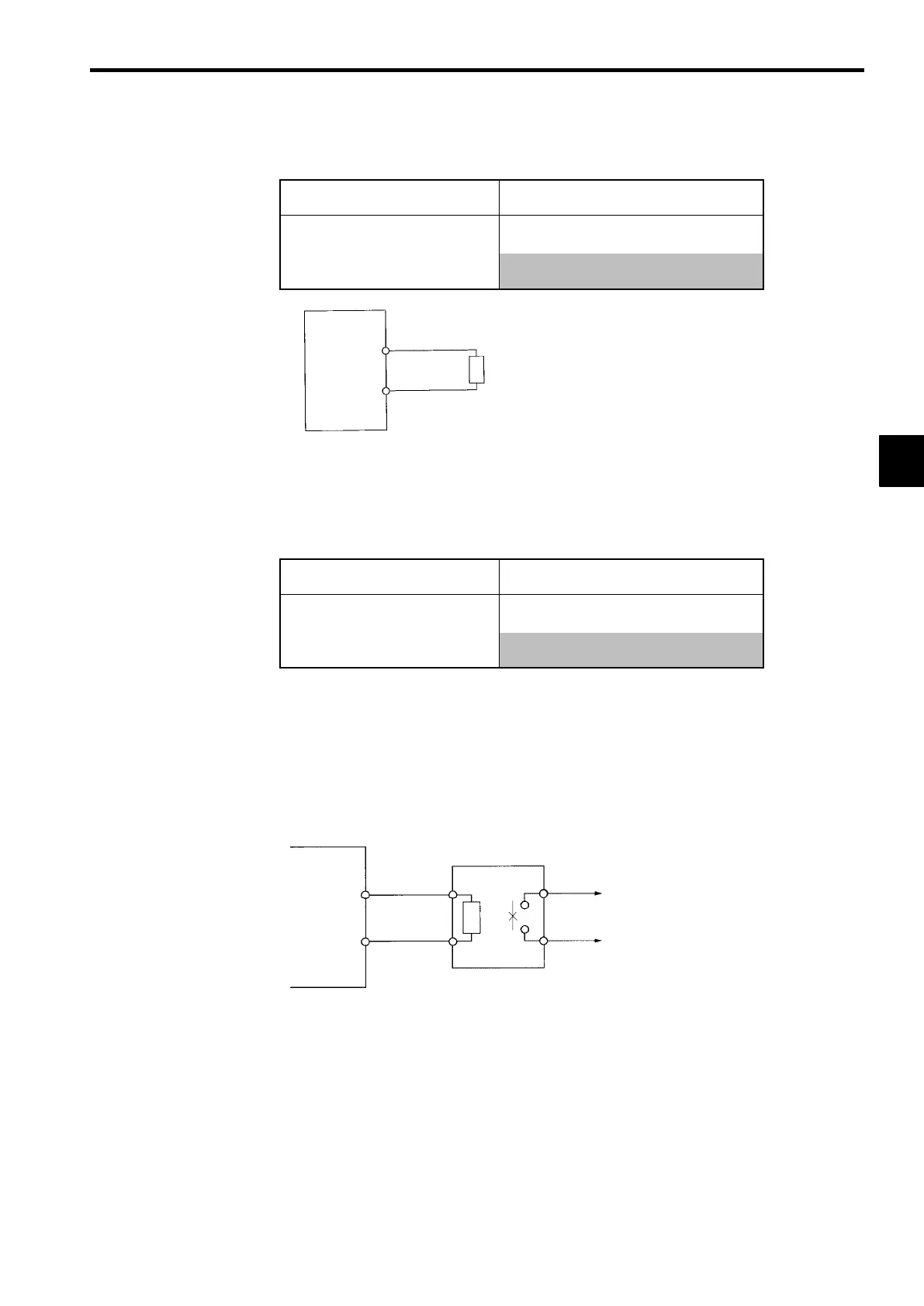
Connect the braking resistor as shown in Figure 3.14.
L8-01 (Overheat protection of braking
resistor)
1 (Enables overheat protection)
L3-04 (Stall prevention during decelera-
0 (Disables stall prevention function)
(Select either one of them.)
3 (Enables stall prevention function with braking
resistor)
VS-616G5
B1
B2
Braking resistor
The braking resistor connection terminals are
B1 and B2. Do not connect to any other termi-
nals. Connecting to any terminals other than
B1 or B2 can cause the resistor to overheat,
resulting in damage to the equipment.
Fig 3.14 Connecting the Braking Resistor
J
Connecting the Braking Resistor Unit (LKEB) and Braking Unit (CDBR)
Connect the Braking Resistor Unit and Braking Unit to the Inverter as shown in the Figure 3.15.
L8-01 (Overheat protection of braking
resistor)
0 (Disables overheat protection)
L3-04 (Stall prevention during decelera-
0 (Disables stall prevention function)
(Select either one of them.)
3 (Enables stall prevention function with braking
resistor)
Set L8-01 to “1” before operating the Inverter with the braking resistor without thermal overload relay trip
contacts.
The Braking Resistor Unit cannot be used and the deceleration time cannot be shortened by the Inverter
if L3-04 is set to “1” (i.e., if stall prevention is enabled for deceleration).
To prevent the Unit from overheating, design the sequence to turn OFF the power supply for the thermal
overload relay trip contacts of the Unit as shown in Figure 3.15.
200 V Class Inverters with 3.7 to 7.5 kW Output and
400 V Class Inverters with 3.7 to 15 kW Output
VS-616G5
B1
B2
P
B
LKEB Braking Re-
sistor Unit
1
2
Thermal overload
relay trip contact
3
 Loading...