Wiring
3.4.1 Applicable Wire Sizes and Closed-loop Connectors
3-6
3.4 Wiring Main Circuit Terminals
3.4.1 Applicable Wire Sizes and Closed-loop Connectors
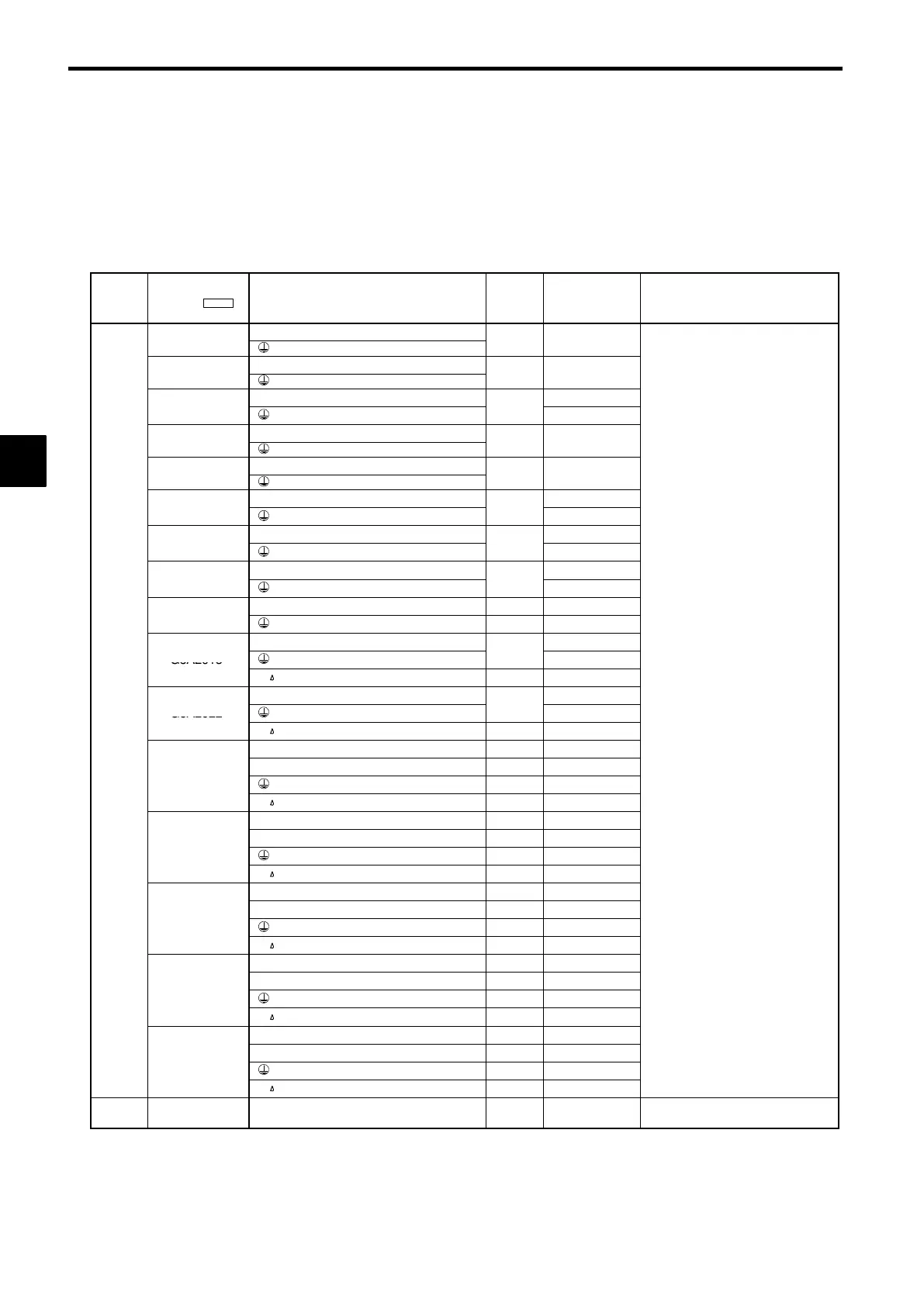
Select the appropriate wires and crimp terminals from Table 3.1 to Table 3.3. Refer to instruction manual
TOE-C726-2j for wire sizes for Braking Resistor Units and Braking Units.
Table 3.1 200 V Class Wire Sizes
Circuit
VS-616G5 Model
CIMR-
Terminal Symbol
Termi-
nal
Screws
Wire Thickness
(see note)
mm
2
Wire Type
R, S, T,
©
,
¨
1,
¨
2, B1, B2, U, V, W
M
to
.
R, S, T,
©
,
¨
1,
¨
2, B1, B2, U, V, W
M
to
.
R, S, T,
©
,
¨
1,
¨
2, B1, B2, U, V, W
2 to 5.5
G5A21P5
M4
3.5 to 5.5
R, S, T,
©
,
¨
1,
¨
2, B1, B2, U, V, W
M
.
to
.
R, S, T,
©
,
¨
1,
¨
2, B1, B2, U, V, W
M
.
R, S, T,
©
,
¨
1,
¨
2, B1, B2, U, V, W
8
G5A25P5
M5
5.5 to 8
R, S, T,
©
,
¨
1,
¨
2, B1, B2, U, V, W
8
G5A27P5
M5
5.5 to 8
R, S, T,
©
,
¨
1,
¨
2,
¨
3, U, V, W
22
G5A2011
M6
8
R, S, T,
©
,
¨
1,
¨
2,
¨
3, U, V, W M8 30
G5A2015
M6 8
R, S, T,
©
,
¨
1,
¨
2,
¨
3, U, V, W
30
G5A2018
M8
14
r, M4 0.5 to 5.5
R, S, T,
©
,
¨
1,
¨
2,
¨
3, U, V, W
38
a
n
Circuits
G5A2022
M8
14
Power ca
es, e.g.,
Vv
ny
pow-
er cables
r, M4 0.5 to 5.5
R, S, T, U, V, W M10 38 to 100
© , ¨ 3
M8 −−
G5A2030
M8 22
r, M4 0.5 to 5.5
R, S, T, U, V, W M10 38 to 100
© , ¨ 3
M8 −−
G5A2037
M8 22
r, M4 0.5 to 5.5
R, S, T, U, V, W M10 60 to 100
© , ¨ 3
M8 −−
G5A2045
M8 22
r, M4 0.5 to 5.5
R, S, T, U, V, W M10 100
© , ¨ 3
M8 −−
G5A2055
M8 30
r, M4 0.5 to 5.5
R, S, T, U, V, W M12 100 to 200
© , ¨ 3
M8 −−
G5A2075
M8 50
r, M4 0.5 to 5.5
Control
Circuits
All models
1to33 M3.5 0.5 to 2 Shielded twisted-pair wires
Note The wire thickness is set for copper wires at 75°C.
Table 3.2 400 V Class Wire Sizes
3
 Loading...