7.2 V/f Control without PG
7-11
7.2 V/f Control without PG
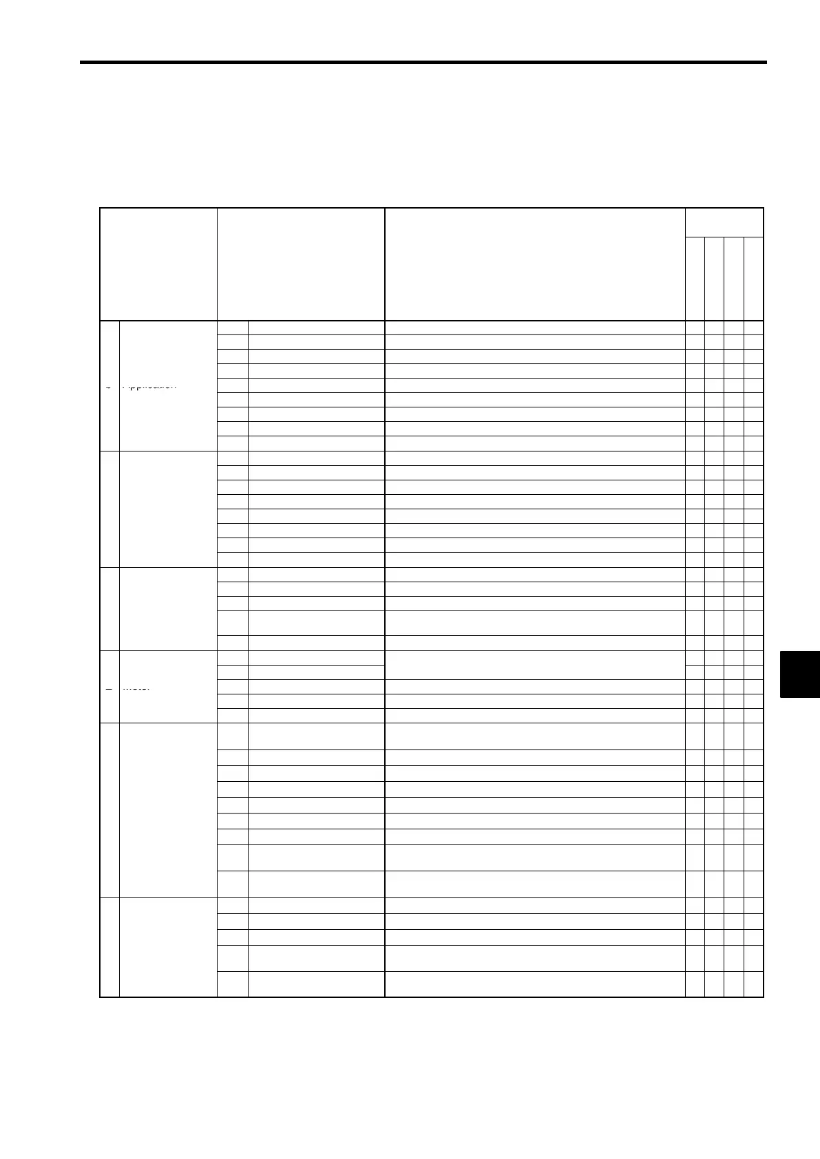
The functions that can be used with vector control without PG are listed in Table 7.2. Details on functions that
are specific to vector control without PG (i.e. those marked with a
L
) are provided in the following table.
Table 7.2 Normal V/f Control Functions
Control Meth-
od
Group Function Comments
V/f
V/f w/PG
Open-loop Vector
Flux Vector
b1 Sequence
Settings such as the reference input method
f f f f
b2 DC Injection Braking
DC injection braking function settings
f f f f
b3 Speed Search
Speed search function settings
f f f f
b4 Delay Timers
Timer function settings
f f f f
b Application
b5 PID Control
PID control settings
f f f f
b6 Dwell Functions
Acceleration/deceleration time dwell function settings
f f f f
b7 Droop Control
Not used. (Can’t be set.)
× × ×
f
b8 Energy Saving
L
Multi-function input: Energy-saving control settings
f f
× ×
b9 Zero Servo
Not used. (Can’t be set.)
× × ×
f
C1 Accel/Decel
Acceleration/deceleration time settings
f f f f
C2 S-Curve Acc/Dec
S-curve characteristics for accel/decel times
f f f f
C3 Motor-Slip Compensation
Slip compensation function settings
f f f f
C4 Torque Compensation
Torque compensation function settings
f f f
×
C Tuning
C5 Speed Controls
Not used. (Can’t be set.)
×
f
×
f
C6 Carrier Frequency
Carrier frequency settings
f f f f
C7 Hunting Prevention
L
Hunting prevention function settings
f f
× ×
C8 Factory Tuning
Not used. (Can’t be set.)
× ×
f
×
d1 Preset Reference
Frequency reference settings (when using Operator)
f f f f
d2 Reference Limits
Frequency upper and lower limit settings
f f f f
d3 Jump Frequencies
Prohibited frequency settings
f f f f
e
erence
d4
Reference Frequence Hold
Function
Up/Down, Accel/Decel stop hold frequency setting
f f f f
d5 Torque Control
Not used. (Can’t be set.)
× × ×
f
E1 V/f Pattern
Motor constant settings
f f f f
E2 Motor Setup
(Motor constants set manually.)
f
f f f
E Motor
E3 Motor 2 Control Methods
Control method settings for motor 2.
f f f f
E4 Motor 2 V/f Characteristics
V/f characteristics settings for motor 2.
f f f f
E5 Motor 2 Motor Constants
Motor constant settings for motor 2.
f f f f
F1
PG speed control card set-
tings
Not used. (Can’t be set.)
×
f
×
f
F2 Analog Reference Card AI User constant settings for an Analog Reference Card
f f f
f
F3 Digital Reference Card DI User constant settings for a Digital Reference Card
f f f
f
F4 Analog Monitor Card AO User constant settings for an Analog Monitor Card
f f f
f
F5 Digital Output Card DO User constant settings for a Digital Output Card
f f f
f
p
ons
F6 Digital Output Card DO User constant settings for a Digital Output Card
f f f
f
F7 Pulse Monitor Card PO User constant settings for a Pulse Monitor Card
f f f
f
F8
SI-F/SI-G Transmission
Card
User constant settings for a Transmission Card
f f f
f
F9
Transmission Cards other
than SI-K2 and SI-F/G
User constant settings for a Transmission Card
f f f
f
H1 Multi-function Inputs Function selection for multi-function inputs
f f f
f
H2 Multi-function Outputs Function selection for multi-function outputs
f f f
f
H3 Analog Inputs Function selection for analog inputs
f f f
f
H Terminal
H4
Multi-function Analog Out-
puts
Function selection for analog outputs
f f f
f
H5
MEMOBUS Communica-
tions
MEMOBUS communications settings
− − −
−
7
 Loading...