Handling Inverters
2-4
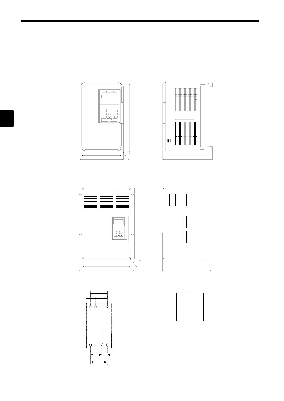
2.2 Exterior and Mounting Dimensions
J
200 V/400 V Class Inverters of 15 kW and Lower
The following diagram shows a 200 V class, 1.5 kW Inverter.
Remove the top and bottom covers when mounting 200 V/400 V class Inverters of 15 kW or lower in a
control panel.
D
H
H1
W1
W
4-d
H2
J
200 V/400 V Class Inverters of 18.5 kW and Higher
The following diagram shows a 200 V class, 18.5 kW Inverter.
D
H
H 1
W1
W
4-d
H2
J
Mounting Dimensions for 400 V Class Inverters of 185 to 300 kW
Max. Applicable Motor
Capacity
[kW]
W1 W2 W3 W4 W5 W6
185, 220
750 440 310 850 285 565
300
750 440 310 873 298 575
2
W1
W4
W5
W6
W2 W3
 Loading...