User Constants
8.2.1 Application Constants: b
8-10
J
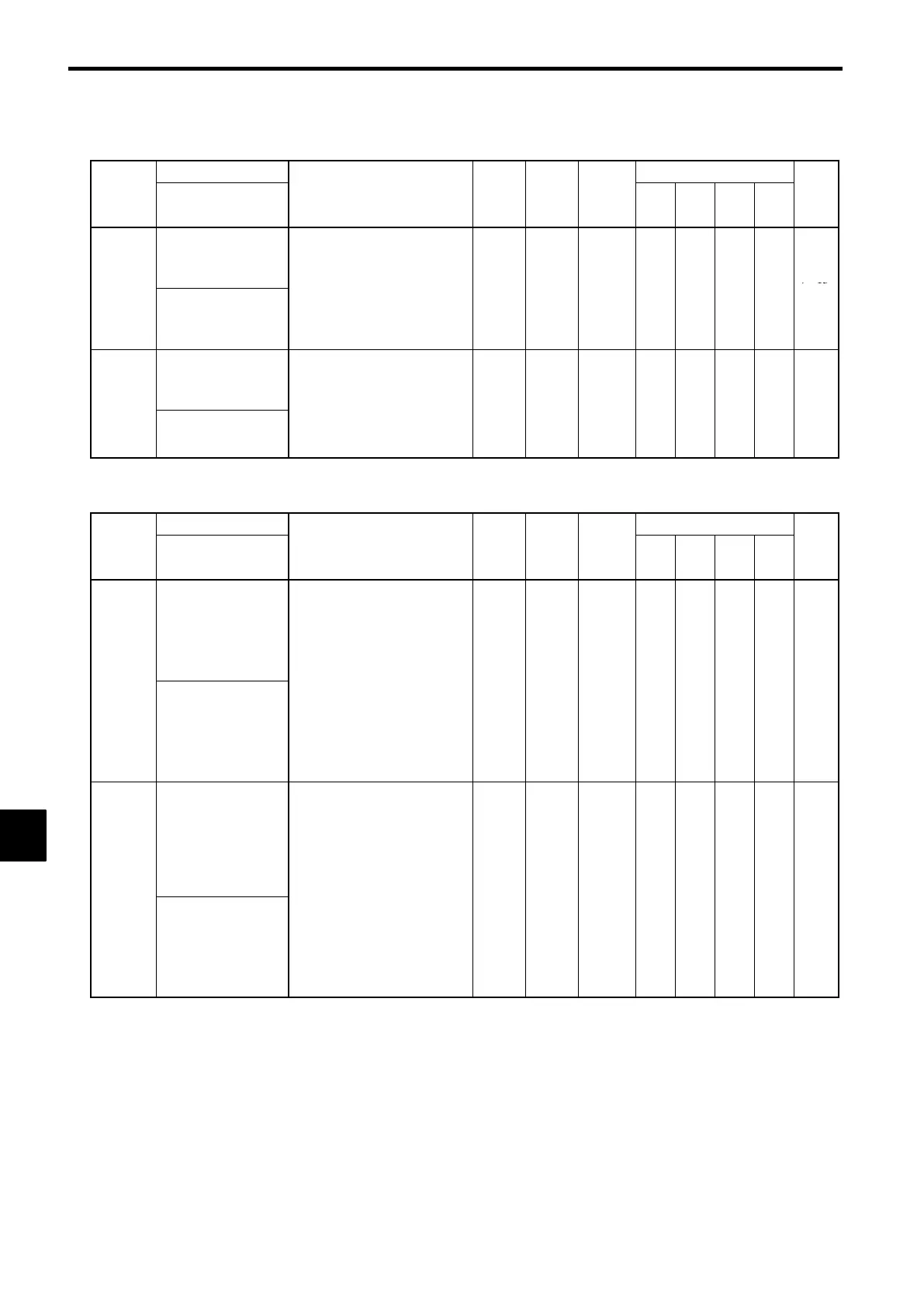
Energy Saving: b8
Name
Change
Control Methods
Constant
Number
Display
Description
Setting
Range
Factory
Setting
during
Opera-
tion
V/f
V/f
with
PG
Open
Loop
Vector
Flux
Vector
Page
Energy-saving gain
Sets the Inverter output voltage
when the energy-saving command
is input.
Enabled when the “ener
-sav-
7-13
b8-01
Energy Save Gain
-
-
ing mode” command is set for
multi-function input. Set as a
percentage of the V/f pattern
voltage.
0 to 100 80
×
A A
× ×
7-38
b8-02
Energy-saving fre-
quency
Sets the energy-saving effective
range minimum frequency in Hz.
:The energy-saving function is
onl
enabled when the fre
uen-
0.0 to
0.0
×
A A
× ×
7-13
Energy Save Freq
-
cy is greater than the energy-
saving frequency and the
speeds are consistent.
400.0
.
7-38
J
Zero Servo: b9
Name
Change
Control Methods
Constant
Number
Display
Description
Setting
Range
Factory
Setting
during
Opera-
tion
V/f
V/f
with
PG
Open
Loop
Vector
Flux
Vector
Page
Zero-servo gain
Used to adjust the strength of the
zero-servo lock.
:Enabled when the “zero-servo
command” is set for the multi-
function input. When the zero-
servo command has been input
and the fre
uenc
reference
b9-01
Zero Servo Gain
drops below excitation level
(b2-01), a position control loop
is created and the motor stops.
Increasing the zero-servo gain
in turn increases the strength of
the lock. Increasing it by too
much will cause oscillation.
0 to 100 5
× × × ×
A
7-19
b9-02
Zero-servo comple-
tion width
Sets the output width of the P-lock
completion signal.
:Enabled when the “zero-servo
completion (end)” is set for a
multi-function input. The zero-
servo completion signal is ON
when the current position is
within the ran
e
the zero-servo
0to
10
× × × ×
A
7-19
Zero Servo Count
-
position + zero-servo comple-
tion width.)
Set the allowable position dis-
placement from the zero-servo
position to 4 times the pulse
rate of the PG (pulse generator,
encoder) in use.
16383
8
 Loading...