6.3.2 V/f Pattern Selection: E1-03
6-22
6.3.2 V/f Pattern Selection: E1-03
User
Change
Valid Access Levels
Constant
Number
Name
during
Opera-
tion
Setting
Range
Unit
Factory
Setting
V/f
Control
V/f with
PG
Open
Loop
Vector
Flux
Vector
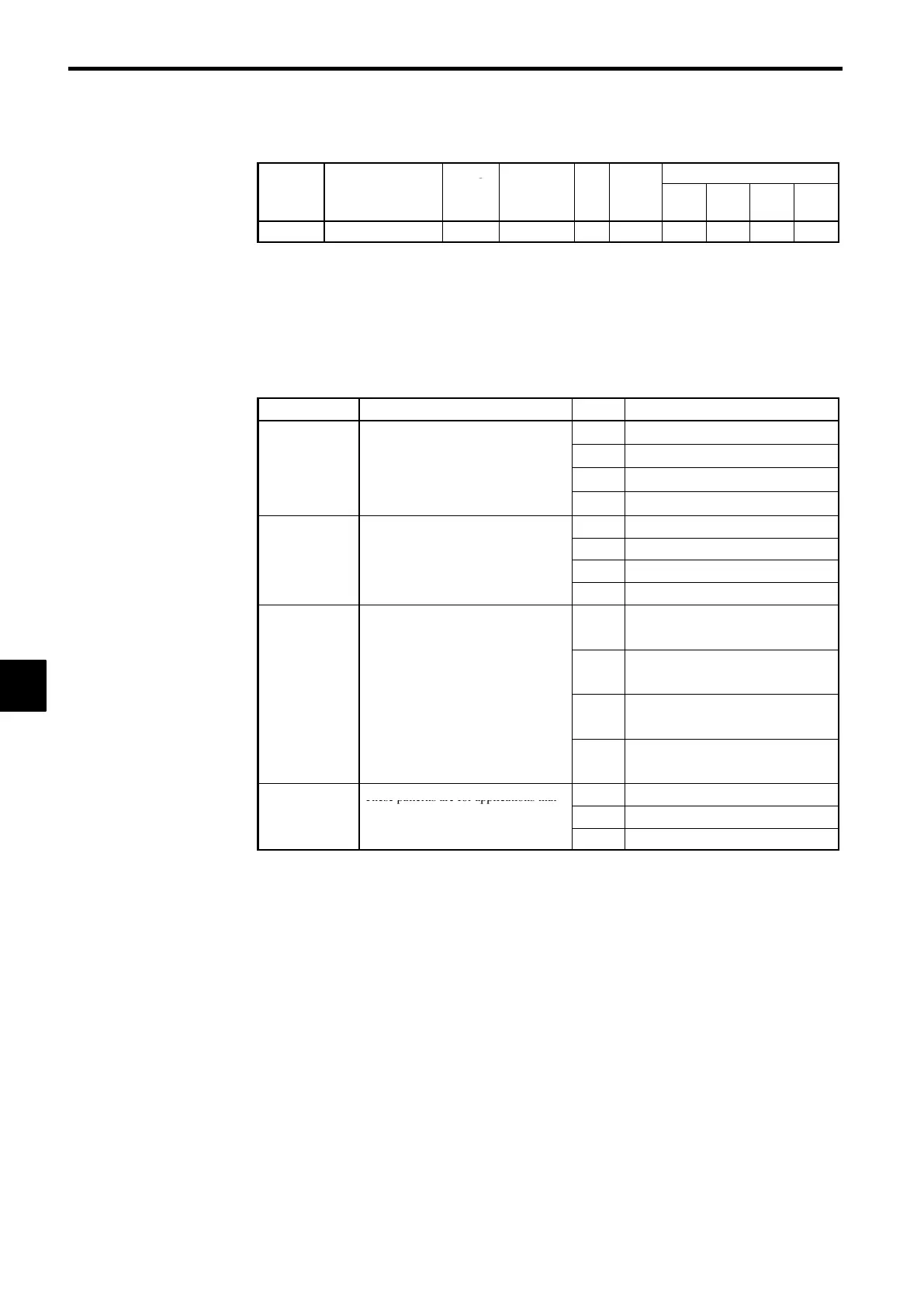
E1-03
V/f pattern selection
×
0toF − F
Q Q
× ×
D
The V/f pattern can be set to any of the following:
• One of 15 preset patterns (settings 0 through E)
• A custom user-set pattern (setting F)
D
The factory setting for E1-03 is “F” (user-defined V/f pattern), but the default contents of this setting
are the same as setting “1.”
J
Selecting a Preset V/f Pattern: E1-03 = “0” through “E”
D
Refer to the following table to set one of the 15 preset patterns.
Characteristics Applications Setting Specifications
These patterns are for general-purpose
0 50 Hz
applications.
Use these
atterns when the load tor
ue
1 60 Hz
Fixed torque
is to remain constant for any rotational
-
-
2 60 Hz, Voltage saturation at 50 Hz
spee
, suc
as
n stra
g
t-
ne convey-
ors.
3 72 Hz, Voltage saturation at 60 Hz
4 50 Hz, cubic
Use these patterns when there is a qua-
dratic or cubic relationshi
between the
5 50 Hz, quadratic
Variable torque
rotational speed and load, such as in
6 60 Hz, cubic
ans or pumps.
7 60 Hz, quadratic
Select a high starting torque V/f pattern
only in the following cases:
8 50 Hz, low starting torque
High starting
S The wiring distance between the In-
verter and motor is relatively large
(greater than 150 m).
9 50 Hz, high starting torque
torque*
S A large torque is required at startup
(such as for heavy axis loads).
S An AC or DC reactor is connected to
A 60 Hz, low starting torque
the Inverter ’s input or output.
S A motor less than the maximum appli-
cable motor is being used.
b 60 Hz, high starting torque
These patterns are for applications that
C 90 Hz, Voltage saturation at 60 Hz
High-speed op-
must rotate at frequencies greater than
-
d 120 Hz, Voltage saturation at 60 Hz
z.
x
v
-
quencies greater than 60 Hz.
E 180 Hz, Voltage saturation at 60 Hz
* Normally it isn’t necessary to use these patterns because starting torque is ensured by auto-
matic torque boost functions.
D
The constant settings for E1-04 through E1-10 will be changed automatically when one of these pat-
terns is selected. There are three possible settings for these constants depending on the Inverter’s ca-
pacity:
• A 0.4 to 1.5 kW V/f pattern
• A 2.2 to 45 kW V/f pattern
• A 55 to 300 kW V/f pattern
D
The characteristics for these patterns are shown in the diagrams on the following pages.
6
 Loading...