7-81
Analog Input Characteristics
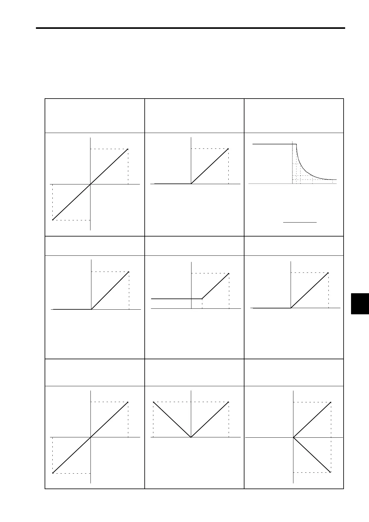
D Analog input characteristics for a gain of 100.0% and a bias of 0.0% are shown for setting examples
in Table 7.12.
D
To set over 100% for a 10 V input (e.g., 300%/10 V), set the gain to 300% in H3-06 for terminal 16
and H3-10 for terminal 14.
Table
7.12
Analog Input Characteristics
S Auxiliary Frequency Reference (Setting: 0)
S Frequency Bias (Setting: 2)
S PID Feedback (Setting: B)
S Frequency reference (H3-09 setting: 1F)
S Frequency Gain (Setting: 1)
S Output Voltage Bias (Setting: 4)
S DC Injection Braking Current (Setting: 6)
S Acceleration/Deceleration Time Gain (Set-
ting: 5)
−10 V
010V
100 %
−100 %
When set to “ 1, ” the setting of H3-02 will be
added to achieve the final gain.
−10 V 0 10 V
100 %
−10 V 0 10 V
100 %
10 %
50 %
20 %
5V1V 2V
=
10V
Input voltage(V)
× 10(%)
(Acceleration/Deceleration Time Gain
between 1 to 10V)
S DC Injection Braking Current (Setting: 6)
S Overtorque Detection Level (Setting: 7)
S Stall Prevention Level (Setting: 8) S Output Frequency Lower Limit (Setting: 9)
S Jump Frequency (Setting: A)
Only the overtorque detection 1 output can be
used when “7” is set to use overtorque detec-
tion for a multi-function output.
−10 V 0 10 V
100 %
3V−10 V 0 10 V
100 %
30 %
−10 V 0 10 V
100 %
S Torque Reference (Setting: 13)
S Torque Compensation Bias (Setting: 14)
S Forward Torque Limit (Setting: 10)
S Reverse Torque Limit (Setting: 11)
S Regenerative Torque Limit (Setting: 12)
S Forward/Reverse Torque (Speed) Limit (Set-
ting: 15)
−10 V
010V
100 %
−100 %
−10 V 0 10 V
100 %
010V
100 %
−100 %
7
 Loading...