7-85
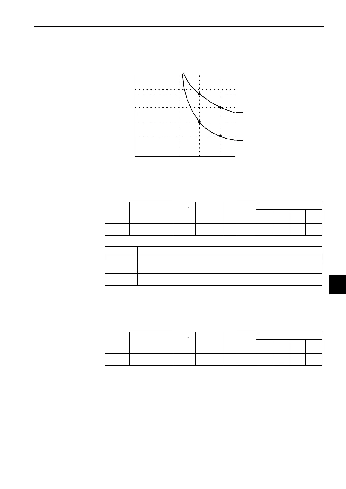
Operating time (minutes)
10
7
3
1
0.4
0.1
0 100 150 200
Cold start
Hot start
Motor current (%)
(E2-01 is 100%.)
Electronic Thermal Time Characteristics
In this example, L1-02 is set to 1 minute, the motor is operating at 60 Hz, and general-purpose
motor characteristics (EI-02=0) are used.
Fig 7.46 Motor Protection Operating Time
J
Momentary Power Loss Settings: L2-01 to L2-05
Momentary Power Loss Detection: L2-01
User
Change
Valid Access Levels
Constant
Number
Name
during
Opera-
tion
Setting
Range
Unit
Factory
Setting
V/f
Control
V/f with
PG
Open
Loop
Vector
Flux
Vector
L2-01
Momentary power
loss detection
×
0to2 − 0
B B B B
D
Settings
Setting Function
0
Disabled. (An undervoltage fault is detected when there is a momentary power loss.)
1
Enabled. (Restarts if power is restored within the L2-02 time. An under-voltage fault is detected
for a longer power loss.)
2
Enabled during CPU operation. (Restarts if power is restored while the CPU is operating. An
undervoltage fault is not detected.)
D
This constant specifies the processing that is performed when a momentary power loss occurs.
D
When power loss ridethru is enabled (setting 1 or 2), operation will be restarted after a speed search
if the power is restored within the allowed time interval.
D
When power loss ridethru is disabled (setting 0), an undervoltage fault will be detected if power is in-
terrupted for more than 15 ms.
Momentary Power Loss Ridethru Time: L2-02
User
Change
Valid Access Levels
Constant
Number
Name
during
Opera-
tion
Setting
Range
Unit
Factory
Setting
V/f
Control
V/f with
PG
Open
Loop
Vector
Flux
Vector
L2-02
Momentary power
loss ridethru time
×
0.0 to 2.0 s 0.7
B B B B
D
The factory setting depends on the Inverter capacity. The factory setting shown in the table is for a 200
V class, 0.4 kW Inverter. (See page 8 - 47.)
D
This setting is valid only when constant L2-01 is set to 1. Set the power loss ridethru time in seconds.
7
 Loading...