8.2 Programming Mode Constants
8-41
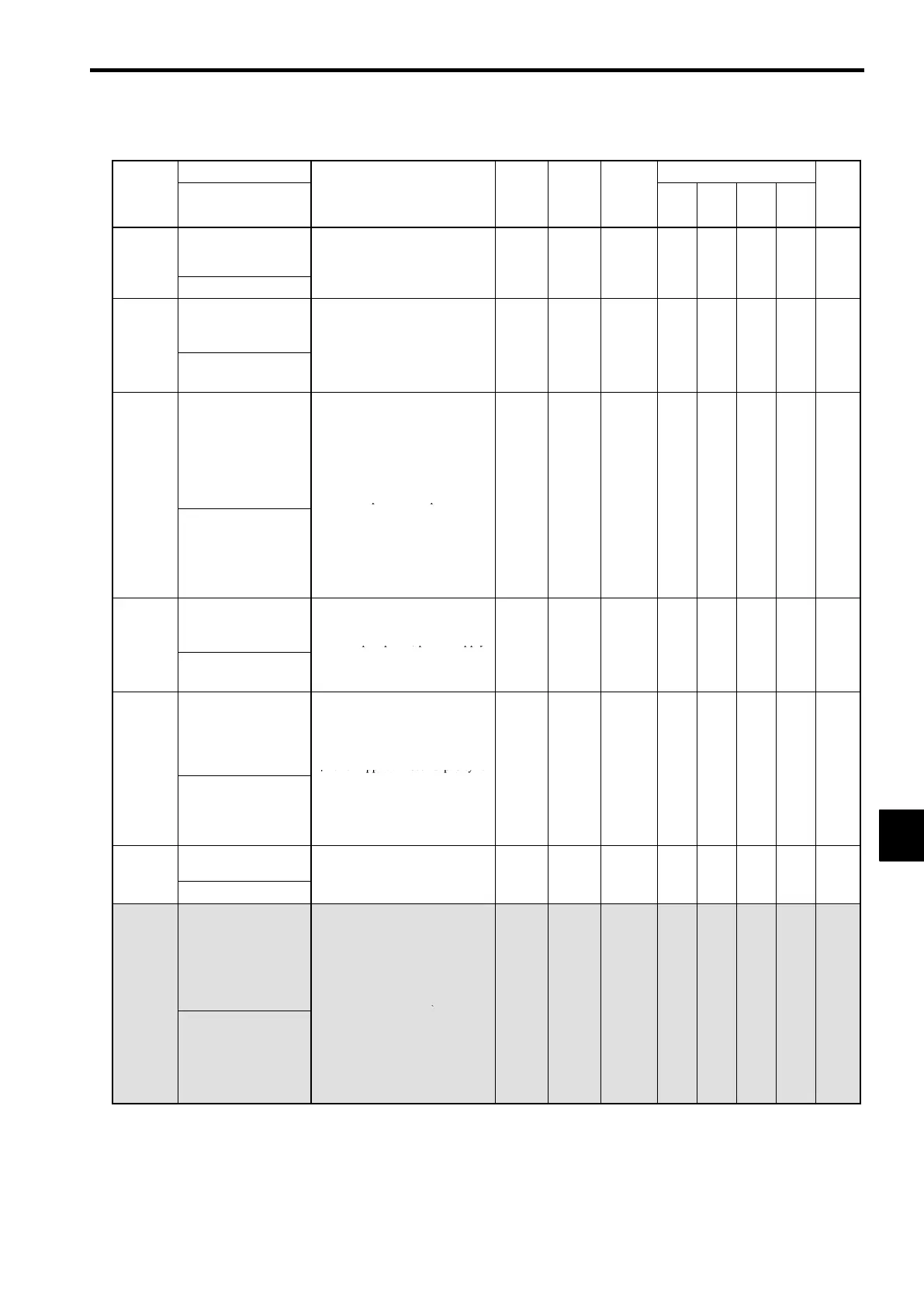
J Hardware Protection: L8
Name
Change
Control Methods
Constant
Number
Display
Description
Setting
Range
Factory
Setting
during
Opera-
tion
V/f
V/f
with
PG
Open
Loop
Vector
Flux
Vector
Page
L8-01
Protect selection for
internal DB resistor
(Type ERF)
0: Disabled (no overheating
protection)
-
0, 1 0
×
B B B B
7-95
DB Resistor Prot
v
-
tion)
L8-02
Overheat pre-alarm
level
Sets the detection temperature for
the Inverter overheat detection
pre-alarm in °C.
50 to
95
×
A A A A
7-95
OH Pre-Alarm Lvl
:The pre-alarm detects when the
cooling fin temperature reaches
the set value.
130
L8-03
Operation selection
after overheat pre-
alarm
Sets the operation for when the In-
verter overheat pre-alarm goes
ON.
0: Decelerate to stop in decelera-
tion time C1-02.
1: Coast to stop
2: Fast stop in fast-stop time
0to3 3
×
A A A A
7-95
OH Pre-Alarm Sel
C1-09.
3: Continue operation (Monitor
display only.)
:A fault will be given in setting
0 to 2 and a minor fault will be
given in setting 3.
L8-05
Input open-phase
protection selection
0: Disabled
1: Enabled (Detects if input cur-
rent open-phase, power supply
0, 1 0
×
A A A A
7-95
Ph Loss In Sel
voltage imbalance or main cir-
cuit electrostatic capacitor de-
terioration occurs.)
,
L8-07
Output open-phase
protection selection
0: Disabled
1: Enabled (Output open-phase
detected at less than 5% of In-
verter rated current.)
:When applied motor capacity is
0, 1 0
×
A A A A
7-95
Ph Loss Out Sel
small for Inverter capacity, out-
put open-phase may be de-
tected inadvertently or open-
phase may not be detected. In
this case, set to 0 (Disabled.)
,
L8-10
Ground protection
selection
0: Disabled
0, 1 1
×
A A A A
−−
Gnd Det Sel
1: Enabled
,
L8-17
Carrier frequency re-
duction selection
0: No carrier frequency reduction
1: With carrier frequency reduc-
tion
2: For factory adjustments
3: For factory adjustments
:If the metallic noise (carrier
0to3 1
×
A A A
×
7-95
L-Spd IGBT Prtct
noise) generated from the mo-
tor at low speeds (less than 6
Hz) becomes a problem, set
L8-17 to 0 and L8-19 to 1.
However, do not set L8-17 or
L8-19 to 0 when using V/f and
open-loop vector control.
8
 Loading...