7.5.6 Protective Functions: L
7-84
Communications Error Detection: H5-05
D
Set whether or not to detect a communications timeout as a communications error.
User
Change
Valid Access Levels
Constant
Number
Name
during
Opera-
tion
Setting
Range
Unit
Factory
Setting
V/f
Control
V/f with
PG
Open
Loop
Vector
Flux
Vector
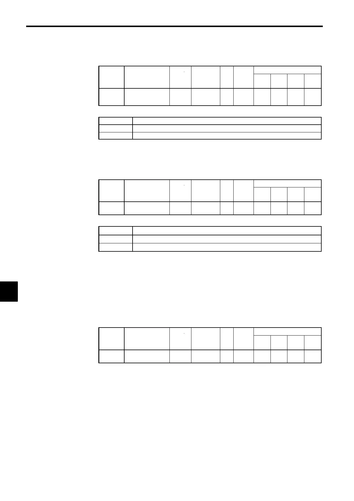
H5-05
Communication er-
ror detection selec-
tion
×
0, 1 − 1
A A A A
D
Settings
Setting Function
0
Do not detect as communications error.
1
Detect as communications error.
7.5.6 Protective Functions: L
J
Motor Protection Settings: L1-01, L1-02
Motor Protection Selection: L1-01
User
Change
Valid Access Levels
Constant
Number
Name
during
Opera-
tion
Setting
Range
Unit
Factory
Setting
V/f
Control
V/f with
PG
Open
Loop
Vector
Flux
Vector
L1-01
Motor protection
selection
×
0, 1 − 1
B B B B
D
Settings
Setting Function
0
Disabled.
1
Enabled.
D
This setting enables or disables the motor overload protection function.
D
The rated current setting (E2-01) is used as a basis for overload detection.
D
Disable the motor protection function (setting 0) when two or more motors are connected to a single
Inverter. Use another method to provide overload protection separately to each motor, such as connect-
ing a thermal overload relay to the power line of each motor.
D
The motor protection function may not protect a motor when the power supply is turned ON and OFF
frequently, because the thermal value is reset each time that the power is turned OFF.
D
If the Overload OL1 alarm (1F) is set in one of the multi-function outputs (H2-01 to H2-03), the output
will be turned ON when the electronic thermal value reaches 90% of the overload detection level.
Motor Protection Time Constant: L1-02
User
Change
Valid Access Levels
Constant
Number
Name
during
Opera-
tion
Setting
Range
Unit
Factory
Setting
V/f
Control
V/f with
PG
Open
Loop
Vector
Flux
Vector
L1-02
Motor protection
time constant
×
0.1 to 5.0
Min-
utes
1.0
B B B B
D
Normally it isn’t necessary to change this setting. (The factory setting is a 150%, 1 minute capacity.)
D
Set the electronic thermal protection operation time if a 150% overload is applied after operating con-
tinuously at the motor’s rated current (hot start).
D
When the motor’s overload capacity level is known, set the hot-start overload resistance level for the
motor, but be sure to allow some margin for safety.
D
Decrease this setting when you want to detect an overload more quickly.
7
 Loading...