User Constants
8.2.1 Application Constants: b
8-8
J
PID Control: b5
Name
Change
Control Methods
Constant
Number
Display
Description
Setting
Range
Factory
Setting
during
Opera-
tion
V/f
V/f
with
PG
Open
Loop
Vector
Flux
Vector
Page
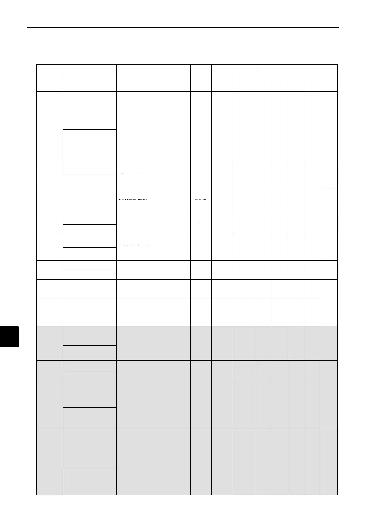
b5-01
PID control mode
selection
0: Disabled
1: Enabled (Deviation is D-con-
trolled.)
2: Enabled (Feedback value is D-
controlled.)
0to4 0
×
A A A A
7-49
PID Mode
:
contro
ena
e
requency
command + PID output, D
control of deviation)
4: PID control enabled (frequency
command + PID output, D
control of feedback value).
Proportional gain (P)
Sets P-control proportional gain as
a percentage.
0.00 to
b5-02
PID Gain
:P-control is not performed
when the setting is 0.00.
.
25.00
1.00
f
A A A A
7-49
Integral (I) time
Sets I-control integral time in
1-second units.
0.0 to
b5-03
PID I Time
:I-control is not performed when
the setting is 0.0.
360.0
1.0
f
A A A A
7-49
Integral (I) limit
Sets the I-control limit as a per-
0.0 to
b5-04
PID I Limit
centage of the maximum output
frequency.
100.0
100.0
f
A A A A
7-50
Differential (D) time
Sets D-control derivative time in
1-second units.
0.00 to
b5-05
PID D Time
:D-control is not performed
when the setting is 0.00.
10.00
0.00
f
A A A A
7-49
PID limit
Sets the limit after PID-control as
0.0 to
b5-06
PID Limit
a percentage of the maximum out-
put frequency.
100.0
100.0
f
A A A A
7-50
PID offset adjustment
Sets the offset after PID-control as
− 100.0
b5-07
PID Offset
a percentage of the maximum out-
put frequency.
to
+100.0
0.0
f
A A A A
7-50
b5-08
PID primary delay
time constant
Sets the time constant for low pass
filter for PID-control outputs in
-
0.00 to
0.00
f
A A A A
7-50
PID Delay Time
-secon
un
s.
:Not usually necessary to set.
10.0
.
b5-09
PID output character-
istics selection
Select forward/reverse for PID
output.
0: PID out
ut is forward.
0,1 0
×
A A A A
7-50
Output Level Sel
.
1: PID output is reverse (high-
lights the output code)
,
PID output gain
Sets output gain.
0.0 to
b5-10
Output Gain
.
25.0
1.0
×
A A A A
7-50
b5-11
PID reverse output
selection
0: 0 limit when PID output is neg-
ative.
1: Reverses when PID output is
negative.
0, 1 0
×
A A A A
7-50
Output Rev Sel
.
:0 limit when reverse prohibit is
selected using b1-04.
,
b5-12
Selection of PID feed-
back command loss
detection
0: No detection of loss of PID
feedback.
1: Detection of loss of PID feed-
back.
Operation continues during
detection, with the malfunction-
0to2 0
×
A A A A
7-50
Fb los Det Sel
ing contact not operating.
2: Detection of loss of PID feed-
back.
Coasts to stop during detection,
and fault contact operates.
8
 Loading...