User Constants
8-14
Constant
Number
Page
Control Methods
Change
during
Opera-
tion
Factory
Setting
Setting
Range
Description
Name
Constant
Number
Page
Flux
Vector
Open
Loop
Vector
V/f
with
PG
V/f
Change
during
Opera-
tion
Factory
Setting
Setting
Range
Description
Display
Start torque constant
Sets the start torque constant in
ms units.
C4-05
TorqCmp Delay T
:When set to 0 to 4 ms, the filter
will be invalid.
0 to 200 10
× × ×
A
×
7-9
* When the control method is changed, the Inverter reverts to factory settings. (The open loop vector control factory settings will
be displayed.)
J
Speed Control (ASR): C5
Con-
Name
Change
Control Methods
stant
Num-
ber
Display
Description
Setting
Range
Factory
Setting
during
Opera-
tion
V/f
V/f
with
PG
Open
Loop
Vector
Flux
Vector
Page
C5-01
ASR proportional
(P) gain 1
Sets the proportional gain of the speed
0.00 to
20.00 *
f
×
B
×
B
6-36
ASR P Gain 1
loop (ASR.) 300.00
.
6-44
C5-02
ASR integral (I)
time 1
Sets the integral time of the speed loop
0.000 to
0.500 *
f
×
B
×
B
6-36
ASR I Time 1
(ASR) in 1-second units. 10.000
.
6-44
C5-03
ASR proportional
(P) gain 2
:Usually setting is not necessary.
Set to change the rotational speed gain.
0.00 to
20.00 *
f
×
B
×
B
6-36
ASR P Gain 2
or
ux vec
or con
ro
P=C5-01
I=C5-02
P, I
300.00
.
6-44
C5-04
ASR integral (I)
time 2
For V/f control with PG
P=C5-03
I=C5-04
0.000 to
0.500 *
f
×
B
×
B
6-36
ASR I Time 2
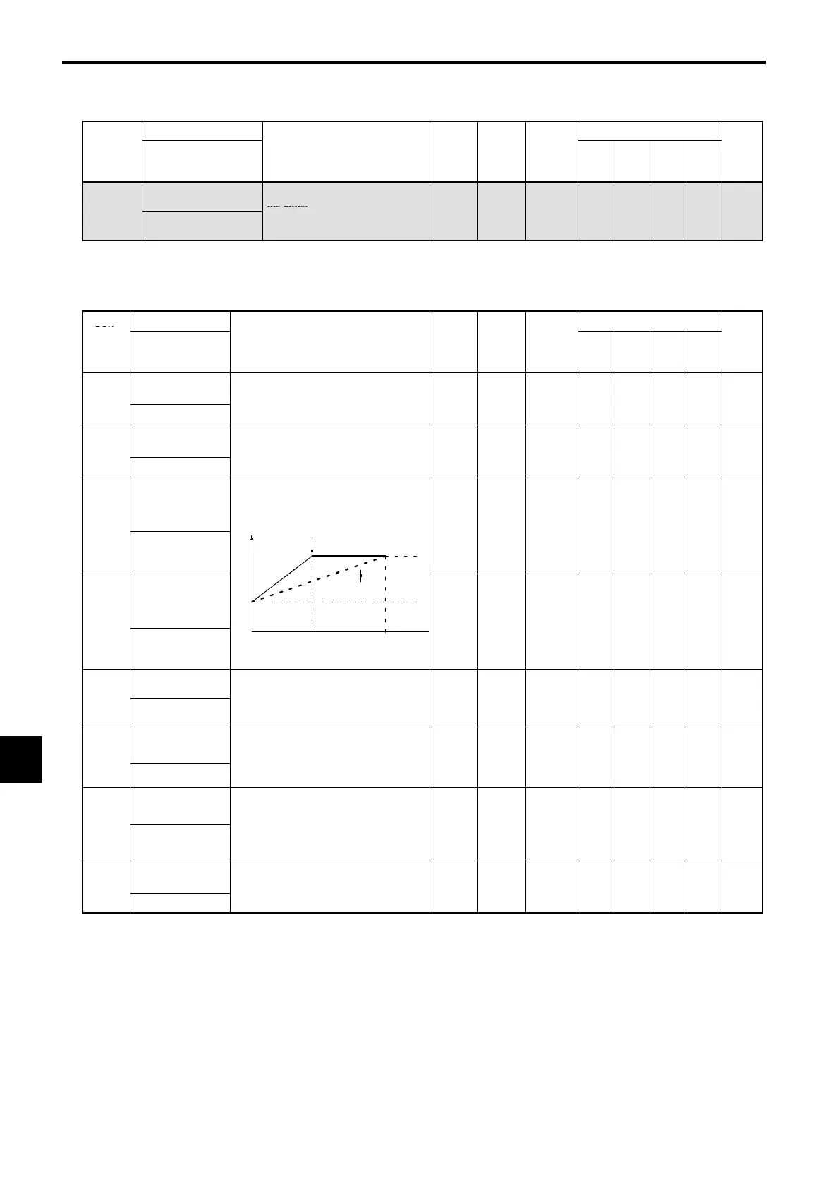
C5-07 E1-04 Motor
speed
(Hz)
0
10.000
.
6-44
ASR limit
Sets the upper limit for the compensation
fre
uenc
for the s
eed control loo
0.0 to
C5-05
ASR Limit
(ASR) to a percentage of the maximum
output frequency.
.
20.0
0.0 *
× ×
A
× ×
6-46
C5-06
ASR primary
delay time
Sets the filter time constant; the time
from the speed loop to the torque com-
-
0.000 to
0.004 *
× × × ×
A
6-37
ASR Delay Time
man
ou
pu
,
nun
so
-secon
.
:
Usually setting is not necessary.
0.500
.
ASR switching
frequency
Sets the frequency for switching between
Proportion Gain 1, 2 and Integral Time 1,
0.0 to
C5-07
ASR Gain SW
Freq
n
zun
s.
:The multi-function input “ASR Gain
SW” takes priority.
.
400.0
0.0
× × × ×
A
6-36
C5-08
ASR integral (I)
limit
Set to a small value to prevent any radi-
cal load chan
e. Set to 100% of the max-
0 to 400 400
× × × ×
A
−−
ASR I Limit
.
imum output frequency.
* When the control method is changed, the Inverter reverts to factory settings. (The open loop vector control factory settings will
be displayed.)
8
 Loading...