4.2 Modes
4-11
4.2.4 Operation Mode
Operation mode is the mode in which the Inverter can be operated.
Many user constants can’t be changed when the Inverter is operating. Refer to User Constant List for de-
tails.
The following monitor displays are possible in operation mode: The frequency reference, output frequen-
cy, output current, and output voltage, as well as fault information and the fault history.
When running the Inverter after using digital operator, press the MENU Key to enter the operation mode and
then press the DATA/ENTER Key from the operation mode display to bring up the monitor display.Run com-
mands can’t be received from any other display. (Monitor display in the operation mode appears when the
power is turned ON.)
J
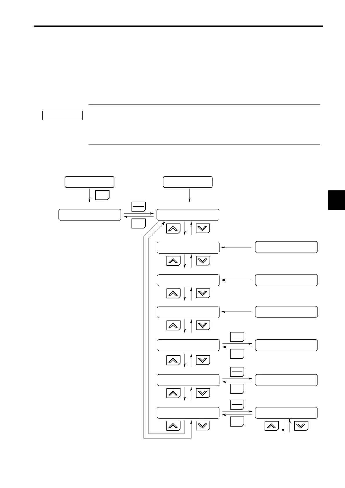
Operations in Operation Mode
Key operations in operation mode are shown in Figure 4.6.
All modes/constants
status
G5: Main Menu :
Operation
Output Freq
U1−02 = 0.00 Hz
Output Current
U1−03 = 0.00 A
Output Voltage
U1−06 = 0.0 VAC
Function U2
Fault Trace
Power ON (when o1-o2=1)
Frequency Ref
U1−01 = 0.00 HZ
Current Fault
None
MENU
ESC
DATA
ENTER
ESC
DATA
ENTER
SOperation Mode
Output frequency display
Output current display
Output voltage display
Function selection U2 (fault trace)
Frequency reference setting/display
Contents of fault trace
Function U3
Fault History
Function U1
Monitor
Last Fault
None
Frequency Ref
U1−01 = 0.00 HZ
ESC
DATA
ENTER
ESC
DATA
ENTER
Function selection U3 (fault history)
Function selection U1 (Monitor)
Contents of fault history
Various monitors
Power ON (when o1-02=12)
Power ON (when o1-02=3)
Power ON (when o1-02=4)
This item can be changed using o1-01
Fig
4.6 Operations in Operation Mode
4
IMPORTANT
 Loading...