7.5.1 Application Constants: b
Advanced Operation
7-48
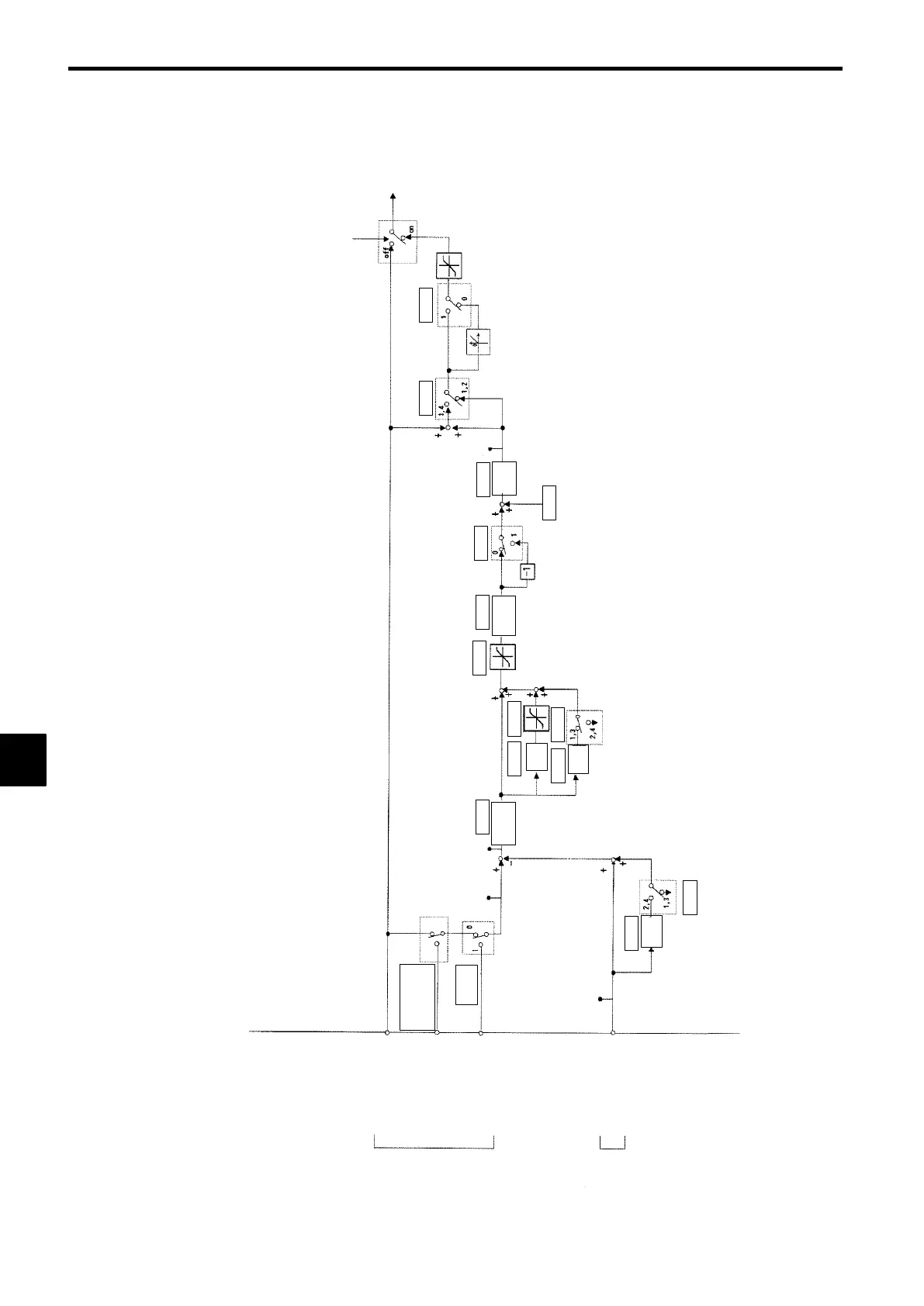
Inverter’s PID Control Function
Figure 7.24 is a block diagram of the Inverter’s internal PID control.
Feedback
value
Target
value
Frequency reference from Option
Card (transmission, AI, DI), terminal
13, Operator, or multi-step speed
reference
Terminal 14 or 16
Multi-function analog input
(Setting: OC)
MEMOBUS communications
(Register No.: 06)
Terminal 14 or 16
Multi-function analog
input (Setting: 08)
OFF when B5=0, at
JOG mode, ow when
multi-function input
(19) is set to OFF.
Frequency
reference
B5 - 11B5 - 01
B5 - 10
B5 - 09
B5 - 08
B5 - 06
B5 - 04
B5 - 03
B5 - 01
B5 - 05
B5 - 02
B5 - 05
B5 - 01
U1 - 38
U1 - 36
U1 - 24
109%
B5 - 07
U1 - 37
Gain
Primary
delay filter
Integral
Proportional
gain
Multi-function
analog input setting
Register
No. bit 1
Differ-
ential
Yes
No
Differ-
ential
Fig 7.24 Block Diagram for PID Control in Inverter
7
 Loading...