6.5 V/f Control with PG
6-43
User
Change
Valid Access Levels
Constant
Number
Name
during
Opera-
tion
Setting
Range
Unit
Factory
Setting
V/f
Control
V/f with
PG
Open
Loop
Vector
Flux
Vector
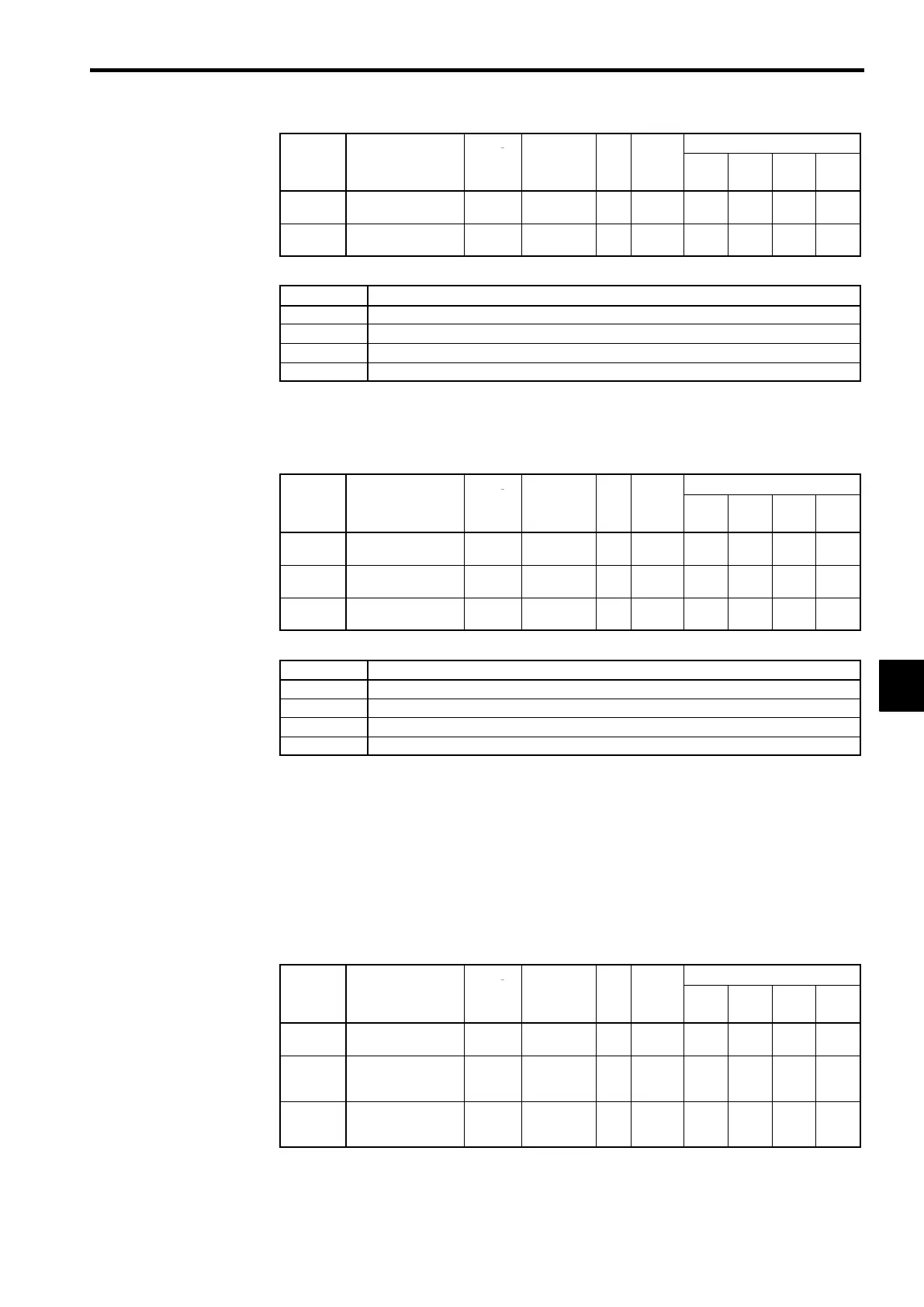
F1-02
Operation selection
at PG open circuit
×
0to3 − 1
×
B
×
B
F1-14
PG open-circuit
detection time
×
0.0 to 10.0 s 2.0
×
A
×
A
D
Settings
Setting Function
0
Deceleration to stop using deceleration time 1 (C1-02).
1
Coast to stop
2
Emergency stop using the emergency-stop time (C1-09).
3
Continue operation (Display “PGO” and continue operation with V/f control.)
Overspeed Settings: F1-03, F1-08, F1-09
D
Overspeed refers to an excessive motor speed.
D
Set the conditions (level and time) for detecting overspeed and the stopping method that is used when
an overspeed is detected.
User
Change
Valid Access Levels
Constant
Number
Name
during
Opera-
tion
Setting
Range
Unit
Factory
Setting
V/f
Control
V/f with
PG
Open
Loop
Vector
Flux
Vector
F1-03
Operation selection
at overspeed
×
0to3 − 1
×
B
×
B
F1-08
Overspeed detection
level
×
0 to 120
%
115
×
A
×
A
F1-09
Overspeed detection
delay time
×
0.0 to 2.0 s 1.0
×
A
×
A
D
Settings
Setting Function
0
Deceleration to stop using deceleration time 1 (C1-02).
1
Coast to stop
2
Emergency stop using the emergency-stop time (C1-09).
3
Continue operation (Display “OS” and continue control.)
D
F1-08 and F1-09 Settings
Constant F1-08 sets the overspeed detection level as a percentage of the maximum output frequency.
Constant F1-09 sets the length of time in seconds that the motor speed must exceed the overspeed
detection level in order to generate an overspeed fault.
PG Speed Deviation Settings: F1-04, F1-10, F1-11
D
After an agreement of the actual motor speed and the reference speed has been detected (depending
on the setting in F1−04), the difference between the actual motor speed (caluculated from the PG feed-
back value) and the frequency reference must exceed the PG speed deviation detection level set in
F1−10 and the allowable time set in F1−11 to detect a PG speed deviation(DEV.)
D
These constants set the conditions (level and time) for detecting PG speed deviation and the stopping
method that is used when a PG speed deviation is detected.
User
Change
Valid Access Levels
Constant
Number
Name
during
Opera-
tion
Setting
Range
Unit
Factory
Setting
V/f
Control
V/f with
PG
Open
Loop
Vector
Flux
Vector
F1-04
Operation selection
at deviation
×
0to7 − 3
×
B
×
B
F1-10
Excessive speed
deviation detection
level
×
0to50 % 10
×
A
×
A
F1-11
Excessive speed
deviation detection
delay time
×
0.0 to 10.0 s 0.5
×
A
×
A
6
 Loading...