Advanced Operation
7.2.3 Setting Motor Constants
7-14
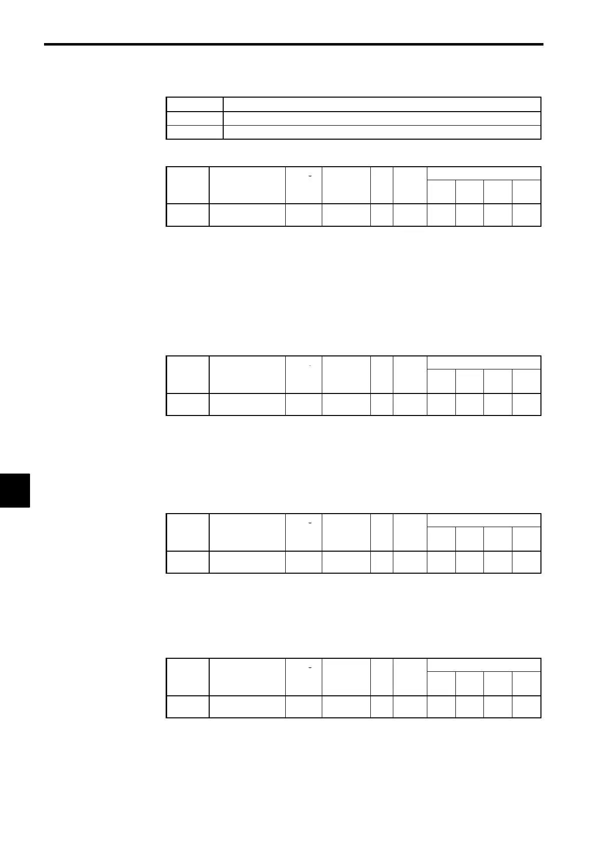
D
Settings
Setting Function
0
Disables the hunting-prevention function.
1
Enables the hunting-prevention function.
J
Hunting Prevention Gain: C7-02
User
Change
Valid Access Levels
Constant
Number
Name
during
Opera-
tion
Setting
Range
Unit
Factory
Setting
V/f
Control
V/f with
PG
Open
Loop
Vector
Flux
Vector
C7-02
Hunting prevention
gain
×
0.00 to 2.50
Mul-
tiple
1.00
A A
× ×
Normally it isn’t necessary to change these constants. Adjust these constants as follows if hunting occurs
with a light load.
D
Increase the setting in C7-02 if oscillation occurs when operating with a light load.
(If the setting is increased too much, the current can fall to the point where stalling occurs.)
D
Decrease the setting in C7-02 if stalling occurs.
D
Disable the hunting-prevention function (C7-01 = 0) if high responsiveness is more important than
suppressing oscillation.
7.2.3 Setting Motor Constants
J
Motor Rated Slip: E2-02
User
Change
Valid Access Levels
Constant
Number
Name
during
Opera-
tion
Setting
Range
Unit
Factory
Setting
V/f
Control
V/f with
PG
Open
Loop
Vector
Flux
Vector
E2-02
Motor rated slip
×
0.00 to
20.00
Hz 2.90
A A Q Q
D
This setting is used as a reference value for the torque compensation function.
D
The default setting depends upon the Inverter capacity.
(The table shows the default settings for 200 V class, 0.4 kW Inverters.) (See page 8 - 47.)
D
Calculate the rated slip (E2-02) from the value shown on the motor nameplate with the following equa-
tion and set this value.
Rated slip = rated frequency (Hz) − rated speed (r/min)
×
number of poles/120
J
Motor No-load Current: E2-03
User
Change
Valid Access Levels
Constant
Number
Name
during
Opera-
tion
Setting
Range
Unit
Factory
Setting
V/f
Control
V/f with
PG
Open
Loop
Vector
Flux
Vector
E2-03
Motor no-load cur-
rent
×
0.00 to
1500.0
A 1.20
A A Q Q
D
This setting is used as a reference value for the torque compensation function.
D
The default setting depends upon the Inverter capacity.
(The table shows the default settings for 200 V class, 0.4 kW Inverters.) (See page 8 - 47.)
D
Set the no-load current (E2-03) at the rated voltage and rated frequency. Normally this value isn’t
shown on the motor nameplate, so it might be necessary to contact the motor manufacturer.
J
Motor Line-to-line Resistance: E2-05
User
Change
Valid Access Levels
Constant
Number
Name
during
Opera-
tion
Setting
Range
Unit
Factory
Setting
V/f
Control
V/f with
PG
Open
Loop
Vector
Flux
Vector
E2-05
Motor line-to-line
resistance
×
0.000 to
65.000
Ω
9.842
A A A A
D
This setting is used as a reference value for the torque compensation function.
D
The default setting depends upon the Inverter capacity.
(The table shows the default settings for 200 V class, 0.4 kW Inverters.) (See page 8 - 47.)
D
Set the motor’s terminal resistance (U−V, V −W, and W−U). Normally this value isn’t shown on the
motor nameplate, so it might be necessary to contact the motor manufacturer.
7
 Loading...