12.4 Wiring Examples
12 - 13
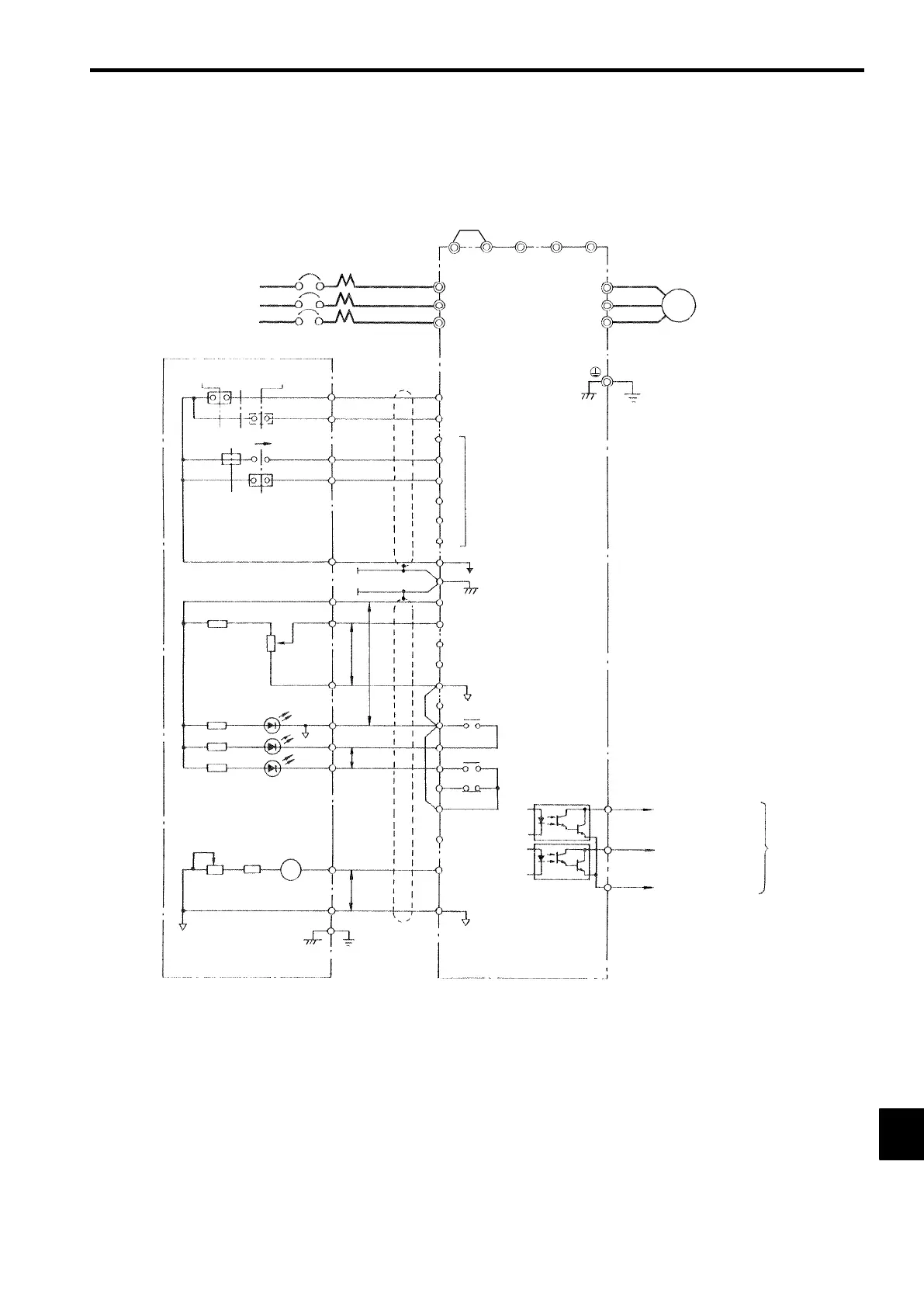
12.4.5 Using a JVOP-95-j, -96-j VS Operator
CIMR-G5A27P5 (200 V class Inverters of 7.5 kW)
Short-circuit bar
(Standard)
©
U (T1)
V (T2)
W (T3)
MCCB
3-phase power
R
S
T
R (L1)
S (L2)
T (L3)
VS-616G5
¨2
Motor
IM
¨1B1B2
(Ground to 100 Ω max.)
3
4
5
6
7
8
Multi-function
contact inputs
11
0V
33 Speed setting power (−15 V, 20 mA)
17
Multi-function contact
output
(Default: Running signal)
9
10
18
19
20
23 Multi-function
analog output
22
21 Multi-function ana-
log output (Default:
Output frequency)
Fault contact output
27
26
25
JVOP-95-j
,
-96
-
j VS Operator
FWD RUN
STOP
REV RUN
1
2
RESET
4
MASTER
AUX 5
11
15
FREQ SET
13
PP
17
SOURCE
9
RUN
10
FAULT
18
P
MTR CAL
Frequency meter
FM
F1
P
F3
E
Forward run command
(forward run when closed)
Reverse run command
(reverse run when closed)
Sequence common (0 V)
12 Shield terminal
15 Speed setting power (15 V, 20 mA)
13 Master speed reference
(0 to 10 V, 20 kΩ)
14 Master speed reference
(4 to 20 mA, 250 Ω)
16 Multi-function analog input
(0 to 10 V, 20 kΩ)
Multi-function
open-collector
output
48 V , 50 mA max.
Multi-function output
common
Open collector 2
(Default: Speed agree
signal)
Open collector 1
(Default: Zero speed
signal)
2
1
12
 Loading...