3
Module Specifications
3.3.3
External Appearance and LED Indicators
3-20
• Self-configuration enables automatic allocation for the Module.
3.3.3 External Appearance and LED Indicators
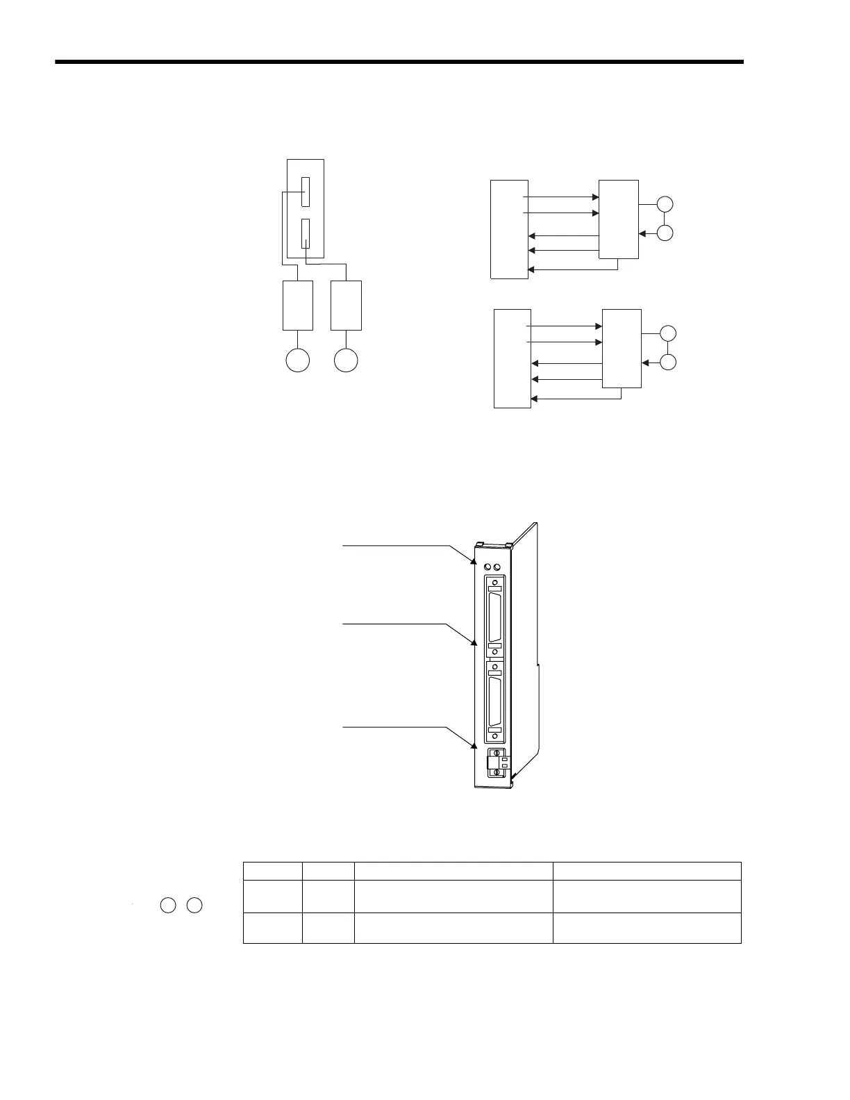
[ a ] External Appearance
The following figure shows the SVA-01 Module external appearance.
[ b ] LED Indicators
The following table shows the SVA-01 Module status when each LED indicator is lit or unlit.
SVA-01
Up to 16 Modules
• Inverters
• Analog Servos
SGDA
SGDB
SGDM
SGDH
SGDS
MM
Speed, Position, and Phase Control
SVA-01
M
PG
Speed reference
SERVOPACK
D/A
Counter
Torque limit
D/A
Encoder pulses
Torque monitor
A/D
Speed monitor
A/D
Torque Control
SVA-01
M
PG
Torque reference
SERVOPACK
D/A
Counter
Speed limit
D/A
Torque monitor
A/D
Encoder pulses
Speed monitor
A/D
SVA-01
LED indicators
Servo connectors
24-V input connector
RUN
CH1
CH2
DC IN
ON
+24V
ERR
Indicator Color Status When Lit Status When Unlit
RUN Green Normal operation Error occurrence
ERR Red Failure (lights/blinks) Normal operation
RUN ERR

 Loading...


