3
Module Specifications
3.4.2
Counter Functions and Settings of LIO-01/LIO-02 Modules
3-38
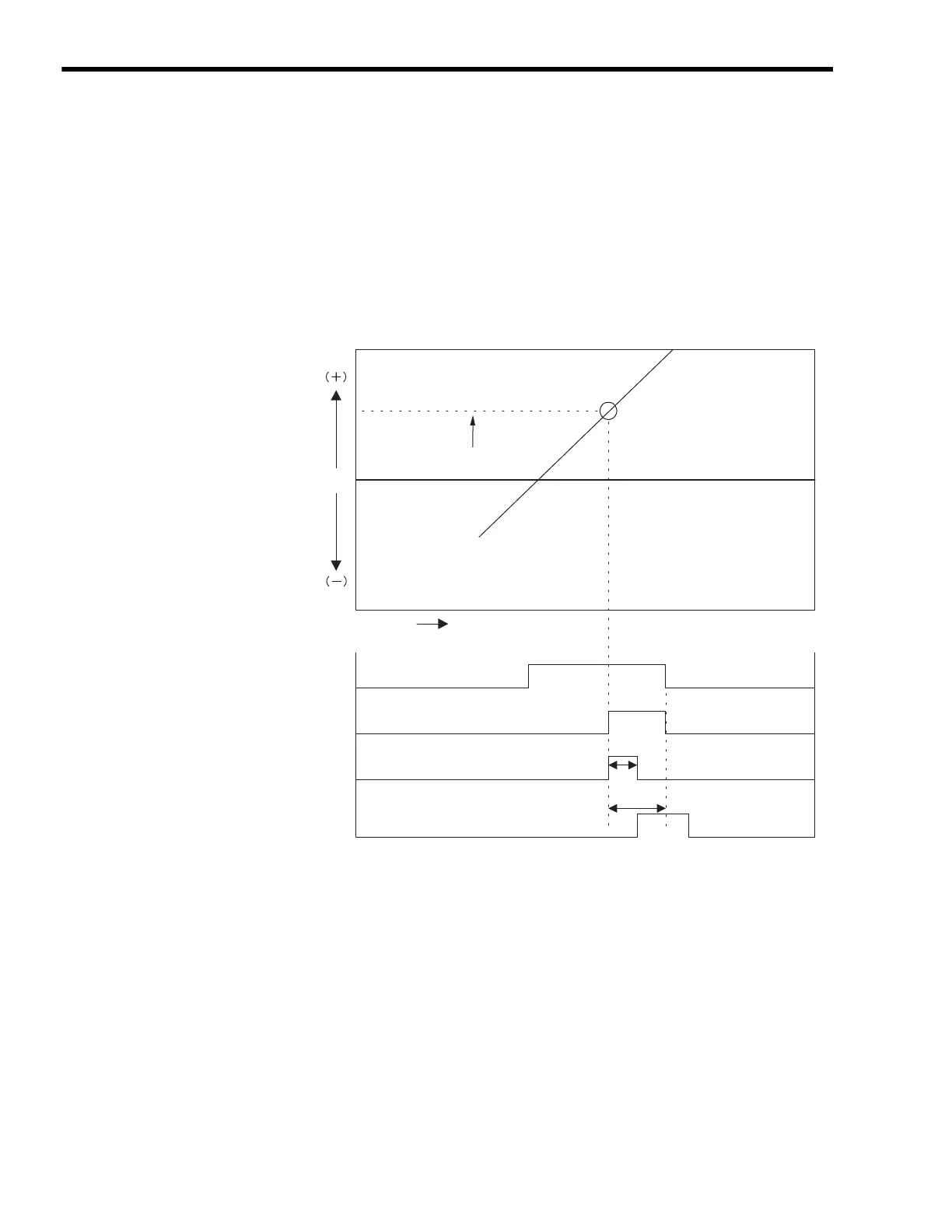
[ c ] Coincidence Output and Coincidence Interrupt Functions
The Coincidence Output and Coincidence Interrupt Functions output an external output signal
(coincidence detection signal) and output an interrupt signal to the MP2300 when the current counter
value and a preset counter setting parameter (Coincidence Detection Setting:
OL
+4) match.
The Coincidence Output Request is enabled when “Use” is set to the counter fixed parameter No. 5
(Coincidence Detection Function Selection).
The Coincidence Interrupt Request is enabled if “Use” is set to the counter fixed parameter No. 6
(Coincidence Interrupt Function Selection).
The following graph shows the changes.
T0: Maximum time from when the MP2300 receives the interrupt request signal to when
interrupt processing is started (70 to 120
µ
s).
TI: Time from when interrupt request signal is received until DWG.I (interrupt process
drawing) execution starts.
DO-00 is used as a coincidence output signal.
When the counter fixed parameter No. 05 (Coincidence Detection Function Selection) is set
to “Use”, DO-00 will be masked. So, when setting a register, which is allocated to DO-00,
using a ladder program to ON or OFF, the setting of this register will not be valid because the
other setting has priority.
To monitor the coincidence detection signal, use Coincidence Detection in the Status of In
Data.
Normal program execution:
Approx. 90 to 170
µs
I/O command executed directly:
Approx. 90 to (1,460 + 40 + N)
µs
N = No. of direct I/O words (Max. 8)
Coincidence point
T0
T1
Interrupt
received
Interrupt request
signal
Coincidence
output signal
Coincidence
detection request
Coincidence detection
set value
0
Time (s)
Counter
current
value

 Loading...


