3
Module Specifications
3.4.2
Counter Functions and Settings of LIO-01/LIO-02 Modules
3-42
4.
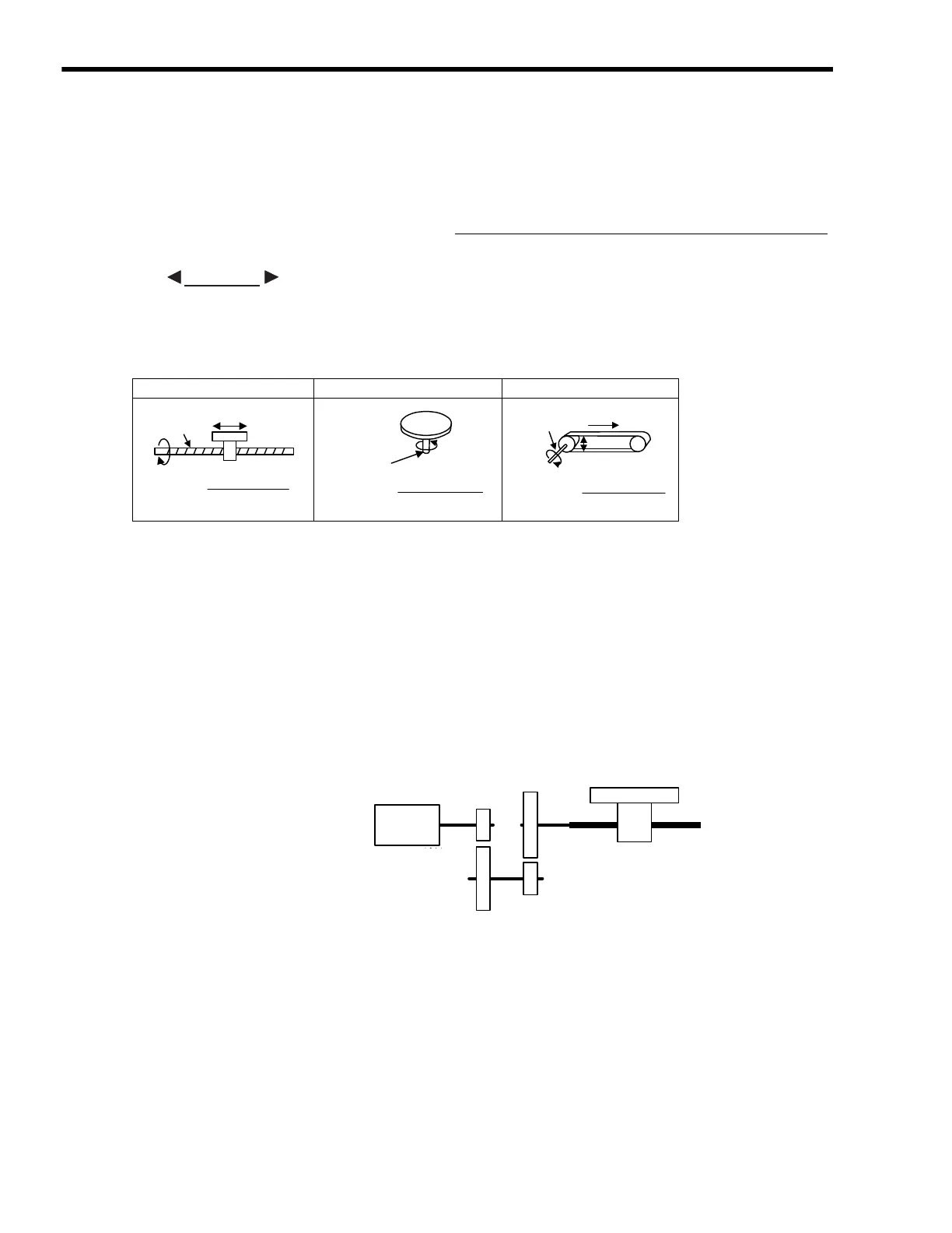
Find the load travel distance for each rotation of the load axis using the reference unit
and set this distance to the counter fixed parameter No. 18 (Moving Amount Per
Machine Rotation).
• Calculation Examples
• For a ball screw pitch of
5 mm and a reference unit of 0.001 mm:
(Reference unit)
5.
Set the Encoder Gear Ratio and the Machine Gear Ratio in the counter fixed
parameters No. 11 and No.12.
When the encoder axis has rotated m times and the mechanical configuration allows the load
axis to rotate n times, set the following values:
No. 11 (Encoder Gear Ratio) = m rotations
No. 12 (Machine Gear Ratio) = n rotations
Setting range: 1 to 65,535 [rotations]
<Setting Example>
For the configuration shown in the diagram:
Gear ratio = n/m = (3/7)
×
(4/9) = 4/21
Therefore, set the following values:
No.11 (Encoder Gear Ratio)
= 4 (rotations)
No. 12 (Machine Gear Ratio)
= 21 (rotations)
Load travel distance per load axis rotation reference unit
Reference unit
Load travel distance per rotation of
load axis (reference unit)
=
EXAMPLE
5
0.001
------------- 5000=
Ball screw Round table
Belt
+ pulley
P
One
rotation
P
Reference unit
=
Load axis
P: Pitch
360°
Reference unit
Load axis
One
rotation
=
Reference unit
Load axis
D: Pulley diameter
D
πD
=
π
D
One
rotation
エンコーダ軸
m回転
7回転
3回転
9回転
4回転
負荷軸
n回転
Encoder axis
m rotations
7 rotations
4 rotations
9 rotations
3 rotations
Load axis n rotations

 Loading...


