3.5
Communication Modules (Optional)
3-55
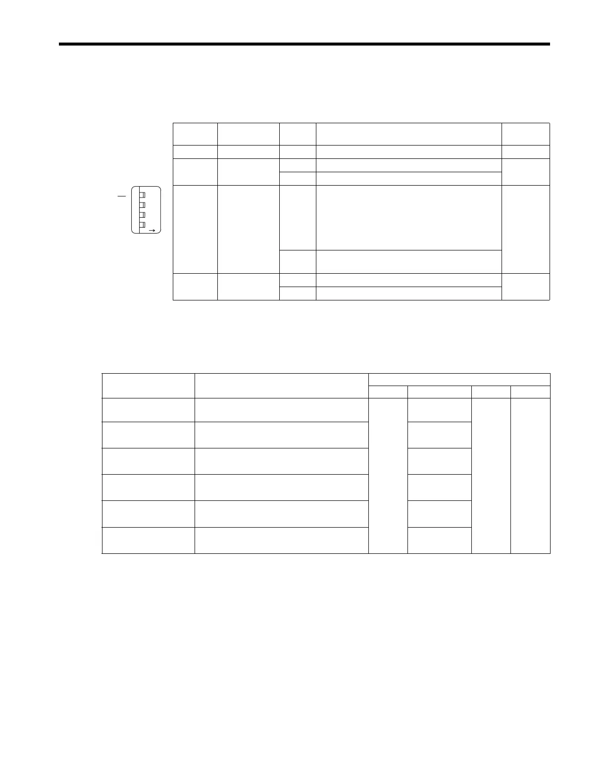
[ b ] Switch Settings
The following table shows the 217IF-01 Module switch settings.
[ c ] Offline Self-diagnostic Test
Turn the TEST switch ON and the INIT switch OFF, and then turn ON the power supply to execute
the Offline Self-diagnostic Test. The following table shows the status of the LED indicators when the
217IF-01 Module detects a malfunction.
* Indicates the number of blinking.
Switch Name Setting Function
Factory
Setting
−
Reserved
−
Always leave set to OFF. OFF
485
485 Mode
ON
Uses the RS422/485 port as an RS485.
OFF
OFF
Uses the RS422/485 port as an RS422.
INIT
Initial Startup
ON
For engineering communications. Starts the RS-
232C (PORT) using default parameters except set-
ting of automatic reception functions. The RS422/
485 port is disabled. Given higher priority than
CPU Module Flash Startup and Self-configuration
Startup.
OFF
OFF
Set to OFF for CPU Module Flash Startup and Self-
configuration Startup.
TEST
TEST
ON
System use
OFF
OFF
Normal operation (Always leave set to OFF.)
TEST
INIT
485
ONOFF
Item Details
LED Indicators
RUN ERR STRX TRX
Flash Checksum
Error
A flash memory checksum error has been
detected.
Not lit
Blinking (once)
∗
Not lit
Depends
on status.
SRAM Error
An SRAM hardware error has been detected.
Blinking
(twice)
∗
DPRAM Error
A DPRAM hardware error has been detected.
Blinking
(3 times)
∗
Communication
Error
A communication error has been detected.
Blinking
(4 times)
∗
RS-232C Error
An RS-232C loopback error has been detected.
Blinking
(5 times)
∗
Watchdog Error
A watchdog timeout error has been detected.
Blinking
(15 times)
∗

 Loading...


