3
Module Specifications
3.5.3
260IF-01 Module
3-58
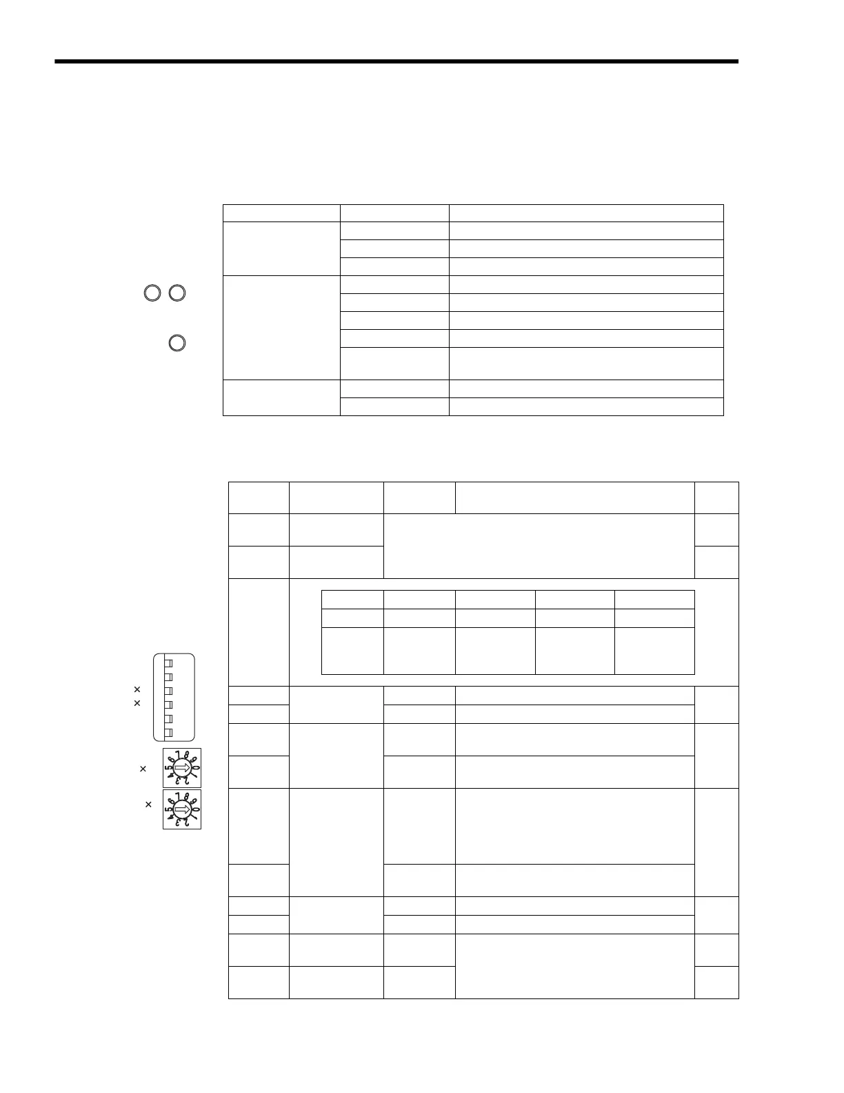
( 2 ) LED Indicators and Switch Settings
[ a ] Indicators
The following table shows the status of the 260IF-01 Module LED indicators.
[ b ] Switch Settings
The following table shows the 260IF-01 Module switch settings.
Indicator Display Status
MS
(2-color LED)
Green Normal operation
Red Module error
Not lit Module power supply disconnected
NS
(2-color LED)
Green Normal operation
Green blinking No I/O allocation, connection being established
Red Error (Bus OFF, duplicated MAC ID)
Red blinking Communication error
Not lit
Communication power supply disconnected, checking
for duplicated MAC ID
STRX
(mounted on PCB)
Green lit/blinking Transmitting or receiving RS-232C data
Not lit No RS-232C data transmission or reception
NSMS
STRX
Switch Name
Status/Set-
ting Range
Function
Defaul
t
DR0
Baud Rate
Setting 0
The following baud rates can be selected by the combination of
ON/OFF settings of DR0 and DR1.
OFF
DR1
Baud Rate
Setting 1
OFF
DR0 OFF OFF ON ON
DR1 OFF ON OFF ON
Baud Rate 125 kbps 250 kbps 500 kbps
Communica-
tion not possi-
ble
×
1
Master/Slave
Mode
ON
Used in master mode.
OFF
OFF
Used in slave mode.
×
2
Self-diagnosis
(DeviceNet)
ON
Executes DeviceNet self-diagnosis when turned
ON the power supply.
OFF
OFF
Does not execute self-diagnosis. Normally,
always leave turned OFF.
INIT
Initial Startup
ON
For engineering communications. Starts RS-
232C (PORT) using default parameters except
setting of automatic reception functions. Given
higher priority than Basic Module Flash Startup
and Self-configuration Startup.
OFF
OFF
Set to OFF for Basic Module Flash Startup and
Self-configuration Startup.
TEST
TEST
ON
System use
OFF
OFF
Normal operation (Always leave set to OFF.)
×
10
Node Address
10s Digit Setting
0 to 6
Set the node address in the range from 1 to 64.
(Rotary decimal switch)
0
×
1
Node Address 1s
Digit Setting
0 to 9 1
TEST
INIT
2
1
DR1
DR0
ON
OFF
10
1

 Loading...


