4.5
Communication Module (Optional) Connections
4-61
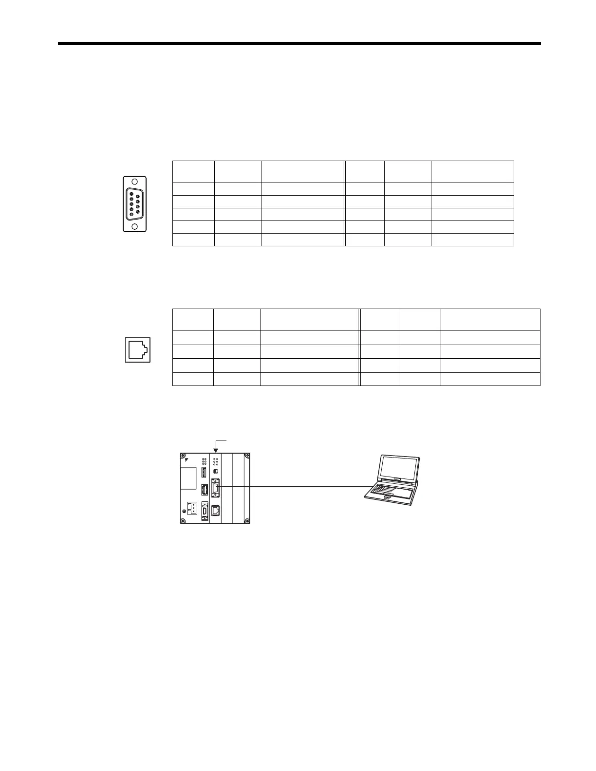
( 3 ) Connector Pin Arrangement
[ a ] PORT Connector
The PORT connector is used to connect the MP2300 to computers and HMI devices via an RS-232C
connection.
[ b ] Ethernet Connector (10Base-T)
The Ethernet connector is used to connect the MP2300 to computers and HMI devices via an
Ethernet (10Base-T) connection.
( 4 ) Module Connection Examples
[ a ] PORT Connector Connections
The following tables show the PORT connector connections based on the device to be connected.
Pin
Number
Signal
Name
Description
Pin
Number
Signal
Name
Description
1FGFrame ground 6 −
2SDSend data 7SGSignal ground (0V)
3RDReceive data 8 −
4RSReady to send 9ERData terminal ready
5CSClear to send
1
69
5
Pin
Number
Signal
Name
Description
Pin
Number
Signal
Name
Description
1
TXD
+
Transmission data + 5
−−
2
TXD
−
Transmission data
−
6
RXD
−
Reception data-
3
RXD
+
Reception data + 7
−−
4
−−
8
−−
MP2300
RS-232C (Max. 15 m)
218IF-01
DC24V
DC 0V
MP2300
YASKAWA
TEST
Option
Option
RDY
ALM
TX
RUN
ERR
BAT
MON
CNFG
INT
SUP
STOP
SW1
OFF ON
BATTERY
CPU I/O
M-I/II
218IF-01
ERR
COL
RX
RUN
STRX
TX
INIT
TEST
ONOFF
PORT
10Base-T

 Loading...


