4.5
Communication Module (Optional) Connections
4-65
( 3 ) Connector Pin Arrangement
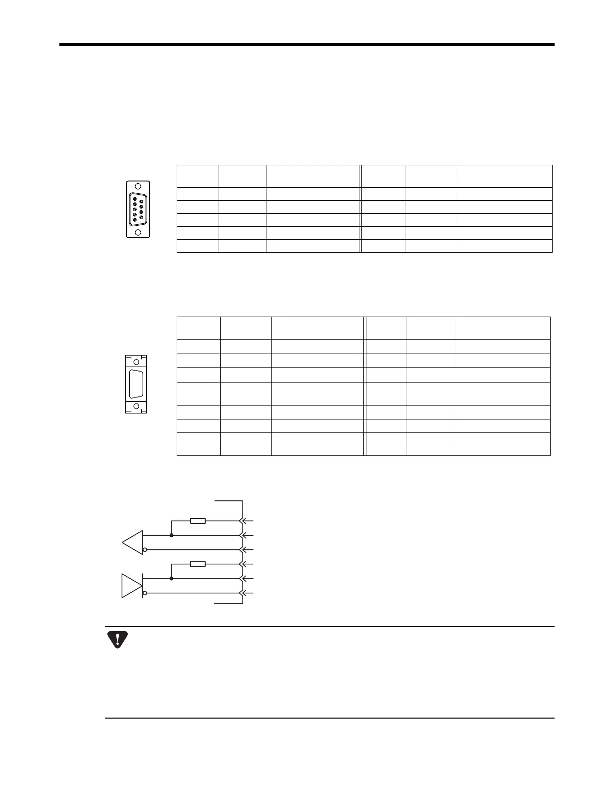
[ a ] PORT Connector
The PORT connector is used to connect the MP2300 to computers and HMI devices via an RS-232C
connection.
[ b ] RS422/485 Connector
The RS422/485 connector is used to connect the MP2300 to computers and HMI devices via an
RS422/485 connection.
Pin
Number
Signal
Name
Description
Pin
Number
Signal Name Description
1FGFrame ground 6 −−
2SDSend data 7SGSignal ground (0V)
3RDReceive data 8 −−
4RSReady to send 9ERData terminal ready
5CSClear to send
1
69
5
Pin
Number
Signal
Name
Description
Pin
Number
Signal
Name
Description
1
TX+
Transmission data + 8
TX+
Transmission data +
2
TX−
Transmission data
−
9
TX−
Transmission data
−
3
RX+
Reception data + 10
RX+
Reception data +
4
RX−
Reception data
−
11
TXR
Transmission data
terminator
5 −− 12
−
−
6
RX−
Reception data
−
13
VCC
Power supply (
+5 V)
7
RXR
Reception data
terminator
14
GND
Ground
1
814
7
Always keep the communication cable separate from the drive, control, power supply, and other transmission
systems.
The maximum length of RS422/485 is 300 m. Keep all cables as short as possible.
The 217IF-01 Module’s RS422/485 interface is not an isolated system. Noise from connected terminals may
cause malfunctions. If malfunctions occur, use a shielded cable, modem, or other measure to reduce noise.
For RS422 connections, add terminator to the reception terminal if required.
For RS485 connections, add terminator to the nodes at both ends of the transmission line.
Terminator
RXR
RX(+)
RX(-)
TXR
TX(+)
TX(-)
7
3,10
4, 6
11
1, 8
2, 9
Terminator has been included, as shown in the
following diagram. If you need to add terminator,
connect RXR to RX (-) and TXR to TX (-).
Leave RXR and TXR open if not adding terminator.

 Loading...


