6
Motion Parameters
6.4.3
Motion Monitoring Parameter Details
6-54
Terminology: Machine Coordinate System
The basic coordinate system that is set according to Zero Point Return (ZRET) command execution or
Zero Point Setting (ZSET) command execution. The MP2300 manages the positions using this machine
coordinate system.
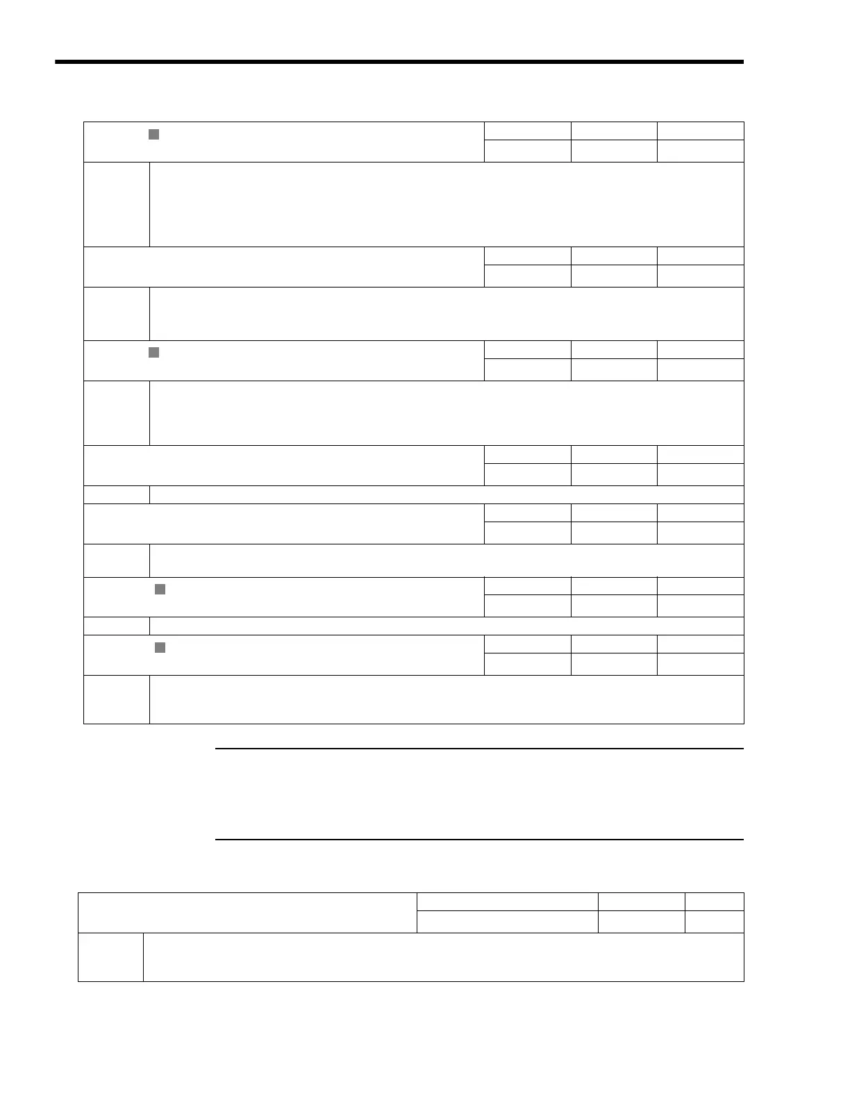
( 11 ) Reference Monitor
IL
12
Machine Coordinate System Position (MPOS)
Setting Range Setting Unit
−
2
31
to 2
31
−
1
Reference unit
Description
Stores the reference position in the machine coordinate system managed by the Motion Module.
・
This parameter will be set to 0 when the power supply is turned ON.
・
This data is not updated when the machine lock mode is enabled. (When the machine lock mode is enabled, the
position reference data is not output externally.)
・
When the machine lock mode function is not used, this position is the same as that in IL
10.
IL
14
32-bit Coordinate System Position (DPOS)
Setting Range Setting Unit
−
2
31
to 2
31
−
1
Reference unit
Description
Stores the reference position in the machine coordinate system managed by the Motion Module.
For a finite length axis, this is the same as the target position (CPOS).
For both finite and infinite length axes, the value is refreshed between
−
2
31
and 2
31
−
1.
IL
16
Machine Coordinate Feedback Position (APOS)
Setting Range Setting Unit
−
2
31
to 2
31
−
1
Reference unit
Description
Stores the feedback position in the machine coordinate system managed by the Motion Module.
・
This parameter will be set to 0 when a Zero Point Return (ZRET) is executed.
・
When an infinite length axis type is selected, a range of 0 to (Maximum Value of Rotary Counter (POSMAX) (fixed
parameter 10)
−
1) is stored.
IL
18
Machine Coordinate Latch Position (LPOS)
Setting Range Setting Unit
−
2
31
to 2
31
−
1
Reference unit
Description
Stores the latch position when the latch has been completed.
IL
1A
Position Error (PERR)
Setting Range Setting Unit
−
2
31
to 2
31
−
1
Reference unit
Description
Stores the following error (Machine Coordinate System Position (IL
12)
−
Machine Coordinate Feedback Position
(IL
16)) managed by the Motion Module.
IL
1C ( only)
Target Position Difference Monitor
Setting Range Setting Unit
−
2
31
to 2
31
−
1
Reference unit
Description
Stores the number of pulses distributed each scan.
IW
1E
POSMAX Number of Turns
Setting Range Setting Unit
−
2
31
to 2
31
−
1
rev
Description
This parameter is valid for an infinite length axis.
The count stored in this parameter goes up and down every time the current position exceeds the Maximum Value of
Rotary Counter (fixed parameter 10).
R
R
R
R
IL
20
Speed Reference Output Monitor
Setting Range Setting Unit
−
2
31
to 2
31
−
1
pulse/s
Description
Stores the speed reference that is being output.
This parameter monitors the speed being output to the MECHATROLINK. This parameter will be 0 for interpolation or
phase control.

 Loading...


