10
Utility Functions
10.1.3
Connections to
Σ
-
I
Series SGDB SERVOPACK
10-4
10.1.3 Connections to
Σ
-
I
Series SGDB SERVOPACK
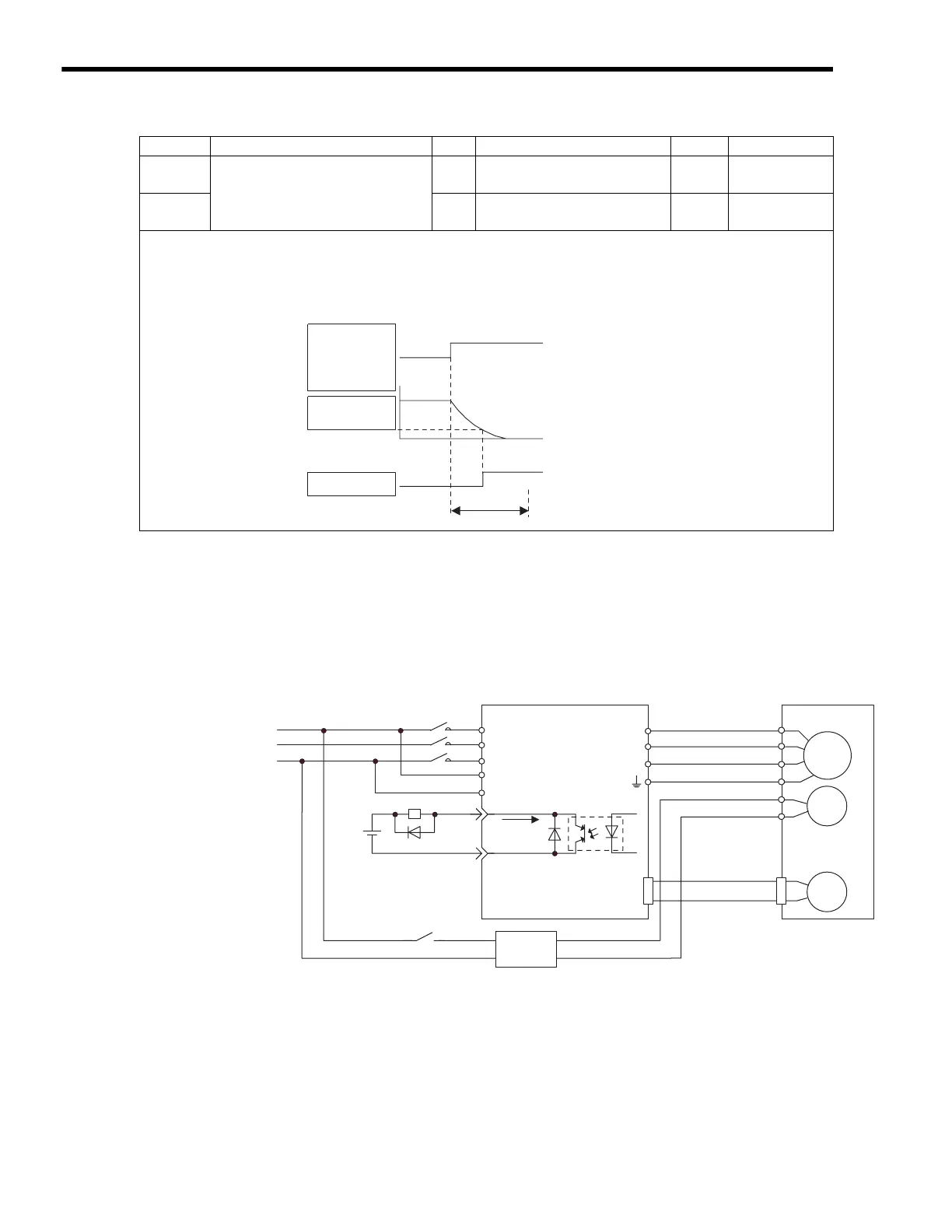
( 1 ) Example of a Brake ON and OFF Circuit
A circuit is configured to turn the brake ON and OFF using the /BK contact output signal from the
SERVOPACK and a brake power supply. The following diagram shows the standard connections.
* 1. The terminal is allocated using parameter Cn-2D. In the example above, /BK signal 4 is set
in the 2nd digit.
* 2. Brake control relay contact
* 3. There are 200-V and 100-V brake power supplies.
Parameter Name Unit Setting/RangeSetting Range Default Control Mode
Pn507
Brake ON Timing when Motor
Running
min
−
1
0 to 10000 100
Speed, torque,
position control
Pn508
10 ms 0 to 100 50
Speed, torque,
position control
Details
Pn507: Speed Level for BK Signal Output when Motor Running
Pn508: Timing of BK Signal Output when Motor Running
These settings are used to set the timing for applying the brake when the Servo turns OFF due to an /S-ON input
signal or alarm.
Motor speed
Pn507
/BK output
Servo ON
Servo OFF
Pn508
Brake holding
/S-ON input or
alarm occurred.
Power OFF
Stop with dynamic
brake or by coasting
(Pn001.0)
Brake
released
The brake on the Servomotor is
designed as a holding brake and it
must be applied only after the motor
has stopped. Adjust this parameter
while observing machine operation.
Power supply
M
BK
PG
U
V
W
CN2
Red
Black
White
AC DC
BK-RY
+24 V
R
S
T
r
t
Brake power supply
SGDB SERVOPACK
27
28
A
B
C
D
E
F
/BK
SG-COM
*
2
*
3
BK-RY
*
1
*
1
50 mA
max.
Blue or
yellow
Servomotor
with a brake

 Loading...


