Installation
32
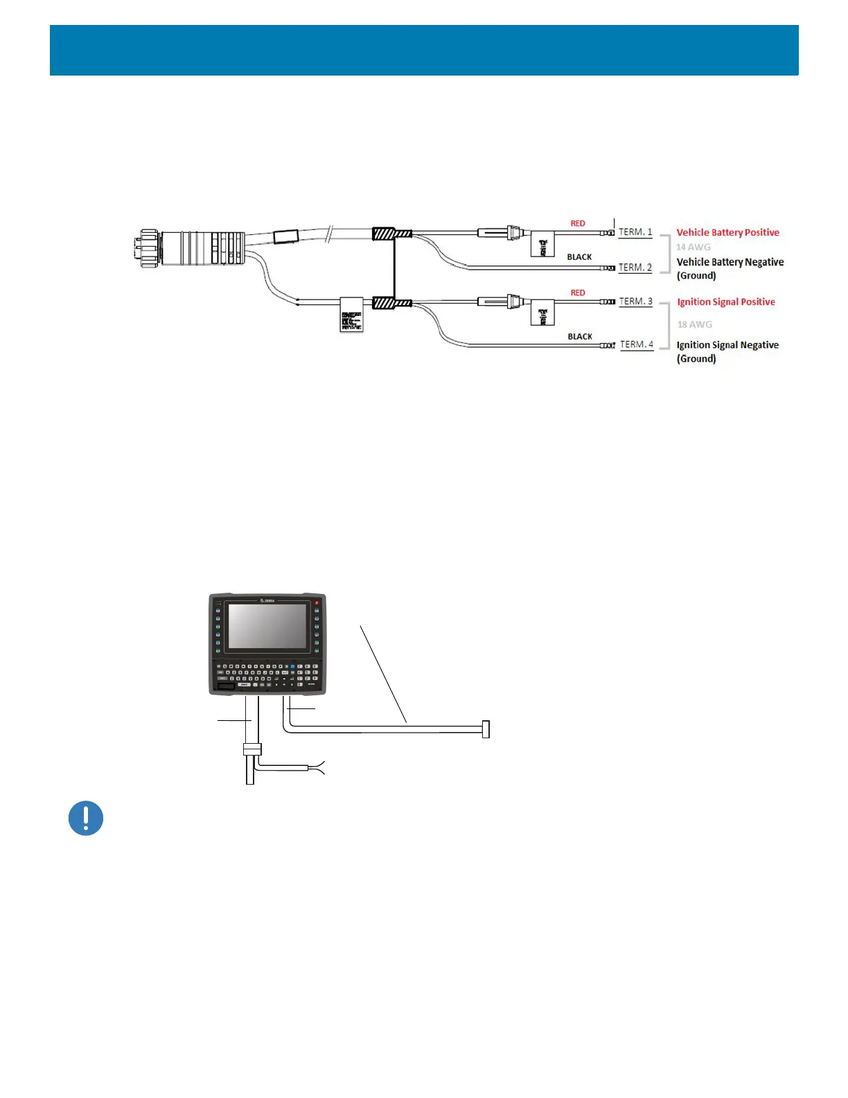
An appropriate fuse type must be used with the power extension cable according to the installation instructions. For the main
power cable, use 3AB, 15A, 250V, slow blow fuse. For ignition sense input, use 3AB, 0.3A, 250V, slow blow fuse.
Figure 11 Power Extension Cable Kit with Optional Ignition Sense Wires (p/n CA1220)
Screen Blanking Wiring
Connecting Switch for Screen Blanking
To use Screen Blanking, connect one of the two DB9 serial ports (using CA1300 Screen Blanking cable) on
the VC8300 to a switch. Activate this switch electrically (e.g. motion sensor) or mechanically (e.g. pedal switch)
when the vehicle is in motion.
Figure 12 Connecting the Switch to the DB9 Cable
IMPORTANT: For customers migrating to the VC8300 from a 8515, 8525, 8535 vehicle mount computer or a 753x hand-held
computer cradle:
If the screen blanking feature was used previously, ensure that you are no longer feeding the screen blanking signals to the
VC8300 main DC power cable. Rewire the screen blanking inputs to the VC8300 DB-9 serial port through the DB-9 screen
blanking cable. In previous generations of vehicle-mount computers, the screen blanking signals were fed in to the terminal
through 2 of the 4 wires in the CPC connector of the DC power cable. This no longer applies for the VC830000.
The screen blanking feature makes use of either one of the DB-9 ports to monitor electrical relay closure.
When enabled, the CTS/RTS pins of the DB9 port are continuously monitored by the screen blanking
application. See Figure 13 for pin configuration.
When the vehicle is in motion, the switch closes the circuit, allowing data packets to be sent or received
through the RTS and CTS pins. The computer detects that the circuit is closed and turns off the screen.
Lines to screen-blanking sensor (optional)
Note: Only CTS and TRTS signals are used.
DB9 Cable
Power Cable
Lines to ignition switch (optional)
User-supplied switch/relay that will provide
an electrical conductive connection when
the vehicle is in motion.