5-66 E6198B Switch/Load Unit User Manual
5 Using Load Cards and Loads
Selecting and Loading Flyback Protection
Coils used as loads may have large flyback voltages, which have
the potential to damage other electronic components. Generally
the UUTs are equipped with flyback protection, so flyback
protection on the load cards is redundant except to provide
backup protection in case you test a defective UUT. If flyback
protection devices are required, you are responsible for
installing them on the load cards.
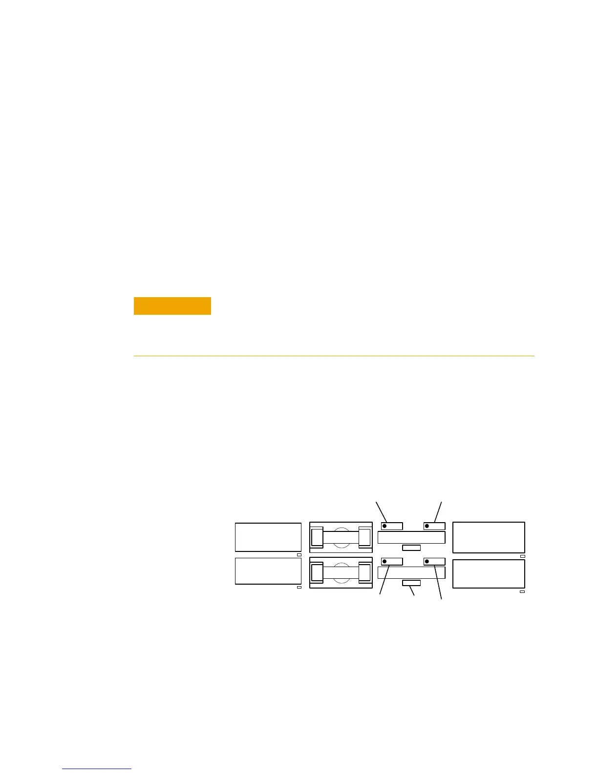
The N9377A load card comes with provisions for user-installed
flyback voltage protection. Figure 5-45 shows a detail of the
first two channels on the component locator diagram of the load
card. It shows the location and polarity orientation for the
channel 1 (RT501 and RT502) and channel 2 (RT503 and RT504)
flyback protection devices when they are installed. This pattern
is repeated for the other fourteen channels.
The flyback protection devices have one flyback protection from
the output to the normally open side of the power switch, and
one flyback protection from the output to the normally closed
side of the power switch.
* The I
2
T figure is an industry standard term. For example, if a fuse with a rating of I
2
T =
100 experiences a current surge of 10A, it can maintain that current for 1 second before its
capacity is exceeded. (10A * 10A * 1 Second = 100)
The load cards are designed for a maximum of 500 V
peak
flyback
voltage. Operating the load cards without flyback protection
installed on the appropriate channels, or with flyback voltages in
excess of 500 V
peak
, may results in damage to the load card or SLU.
Figure 5-45 N9377A Load Card - Flyback Locator and Polarity Orientation
F501
F503
R501
R506
K501
K504
K502
K505
RT501
RT502
R141
R141
RT503 RT503