Using Load Cards and Loads 5
E6198B Switch/Load Unit User Manual 5-9
Selecting a Power Supply Configuration
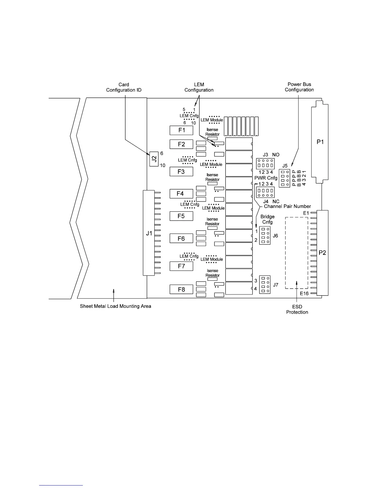
Each channel pair connects to the power bus via a Form C SPDT
(single-pole, double-throw) relay. This relay has an NO
(normally-open) and an NC (normally-closed) terminal. Each
NO terminal is connected to a pin on J3, and each NC terminal
is connected to a pin on J4. Each pin on J3 or J4 can be
connected to any of the four power bus lines on J5 via jumper
wires. This arrangement allows convenient pull-up or pull-down
of the various inputs. It also allows for terminating a UUT load
at a different voltage than ground.
Figure 5-4 Agilent E6175A 8-Channel Load Card Layout