Configuring the Switch/Load Unit 4
E6198B Switch/Load Unit User Manual 4-7
Example B (available only as a special configuration) shows two
isolated power supplies with separate grounds connected to the
power bus. This configuration can be used if, for example, one
supply requires local sensing, while the other requires remote
sensing at the UUT.
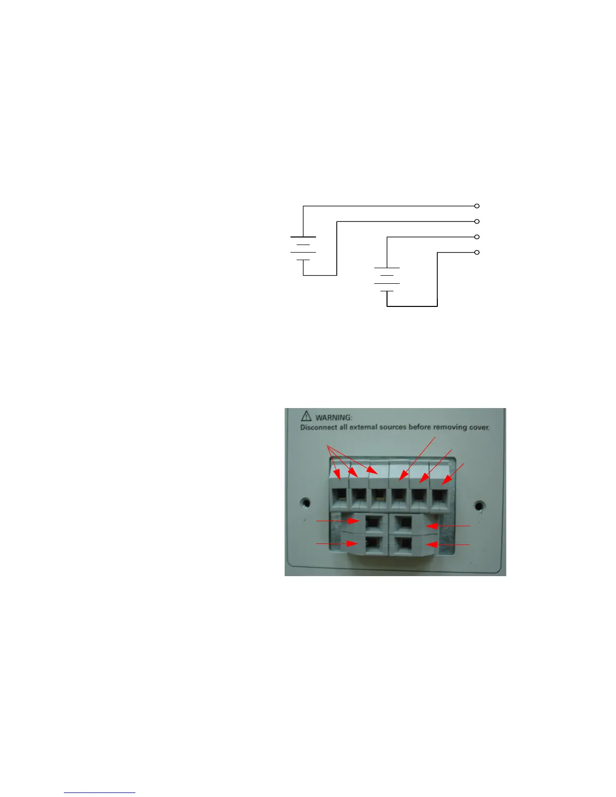
For the standalone SLU, users can directly connect to the
external connector “DC Power Bus Connection”. See Figure 4-7.
Figure 4-6 Example B: Isolated Power Supplies
Figure 4-7 DC Power Bus Connector Of Standalone SLU
Power Bus 1
Power Bus 2
Power Bus 3
Power Bus 4
PB Sense 1
PB Sense 2
PB Sense 3
PB Sense 4