Using Load Cards and Loads 5
E6198B Switch/Load Unit User Manual 5-13
Table 5-2 details the components that need to be
installed/replaced for each of the two channel pairs of the
Agilent E6175A 8-Channel Load Card.
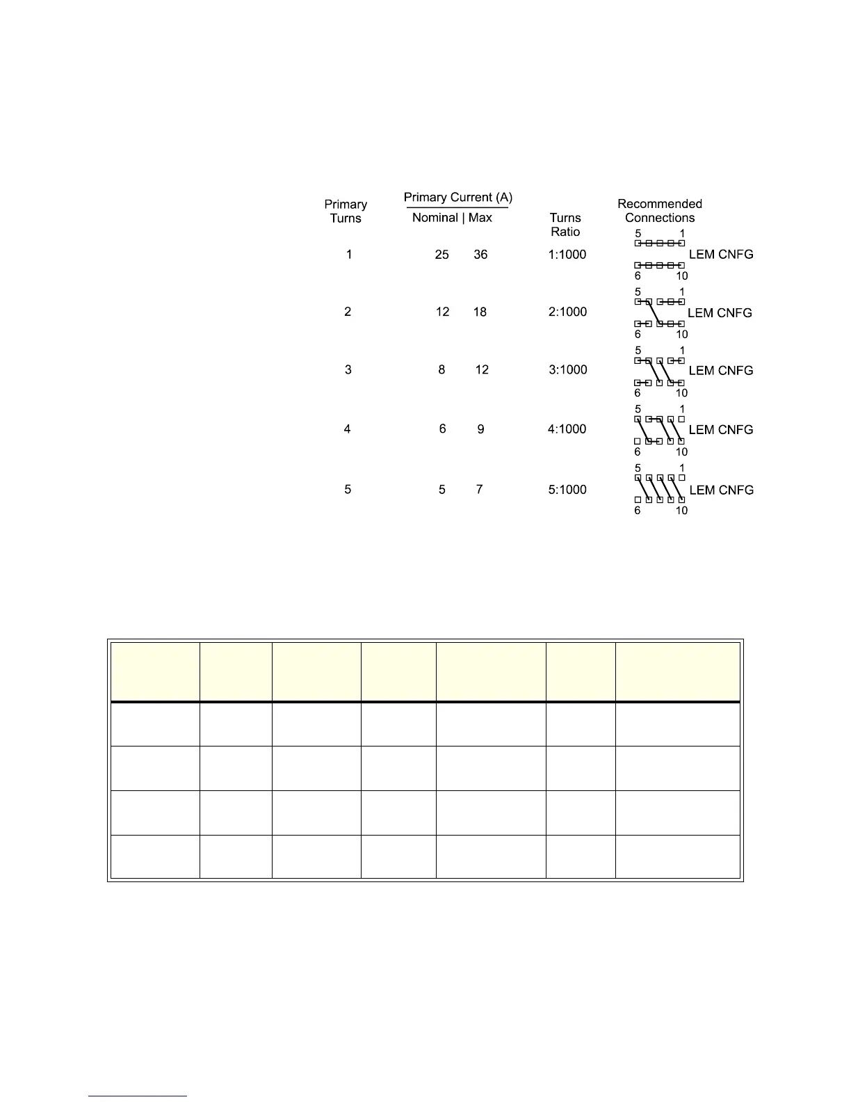
The board was tested with a LEM Model LA25-NP
*
. Additional
information about the use of this current transducer is available
from the manufacturer.
Figure 5-7 Wiring Options of LEM Model LA25-NP Primary for Various
Current Ranges
Table 5-2 Components involved in LEM Module Installation
Channel(s) Isense
Resistor
(Rmvd)
Measuring
Resistor
Shorting
Jumper
Bypass
Capacitors
(0.01 μf)
LEM
Module
LEM Tap
Connection
1, 2 R1 R2 TP41 to
TP42
C41 and C42 U1 See LEM module
Spec. Sheet
3, 4 R3 R4 TP43 to
TP44
C43 and C44 U2 See LEM module
Spec. Sheet
5, 6 R5 R6 TP45 to
TP46
C45 and C46 U3 See LEM module
Spec. Sheet
7, 8 R7 R8 TP47 to
TP48
C47 and C48 U4 See LEM module
Spec. Sheet
* This load card was tested with a LEM Model LA25-NP Current Transducer from LEM USA, Inc. 6643 West
Mill Road, Milwaukee, WI, 53218. (414) 353-0711