3-12 E6198B Switch/Load Unit User Manual
3 Switch/Load Unit and Plug-In Cards
Backplane Connector Name
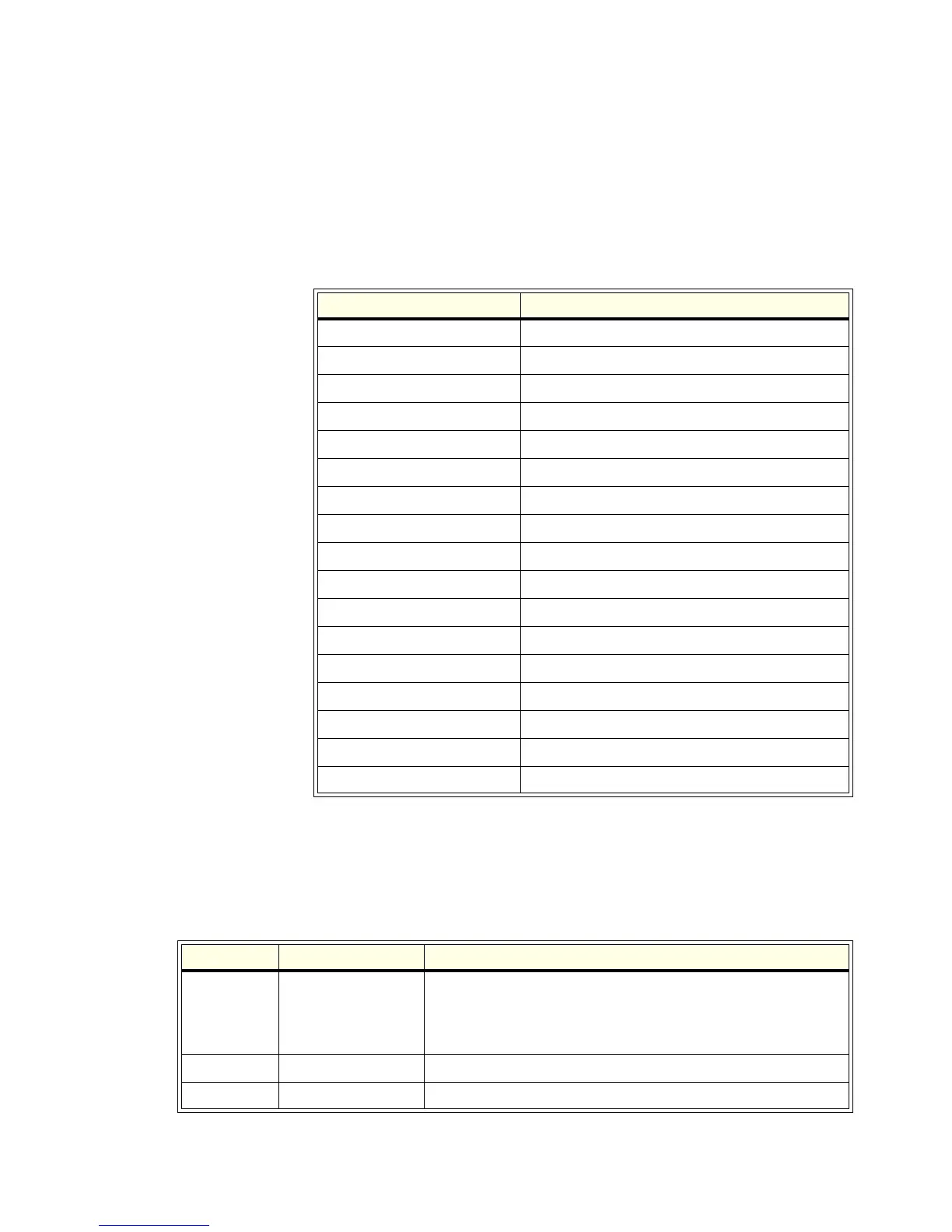
Table 3-3 lists the connectors on a E6198B backplane.
Backplane J1, J2 and J3 Connectors
Table 3-4 shows the factory default configuration for the
backplane connectors.
Table 3-3 Backplane Connectors for E6198B
E6198B Reference Designator Description
J2 SLU Current Sense: Bussed/Split
J3 SLU Power Bus Sense Select: Local/Remote
J1 Frame Select
T1-T14 SLU Logic Power Supply Connector
J101 To USB Controller Connector
J102 Utility Connector
J104 External Reset (reserved)
J105 +5V Indicator (+5V Status)
J106 +12V Indicator (+12V Status)
J107 -12V Indicator (-12V Status)
J108 READY Indicator (Control Status)
J109 +12V Output For Fan
J110 +12V Output For Fan
J111 +12V Output For Fan
J201-J221 Load Card Slots Connector
J801 & J802 Power Busses PB1-PB4
J803 Sense For PB1-PB4
Table 3-4 Backplane Factory Default Connector Settings
Connector Default Setting Description
J1
0 (Zero) Frame Select address 0-7. When using multiple Switch/Load Units
in your test system, Connector J1 provides a unique address for
each Switch/Load Unit. Factory default (one Switch/Load Unit) is
0.
J2 Bussed Switch/Load Unit Current-Sense Bus
J3 Local Switch/Load Unit Power Bus Sense select: Local/Remote