EasyManuals Logo

Agilent Technologies E6198B User Manual

Agilent Technologies E6198B
318 pages
To Next Page IconTo Next Page
To Previous Page IconTo Previous Page
Page #110 background imageLoading...
Page #110 background image
5-42 E6198B Switch/Load Unit User Manual
5 Using Load Cards and Loads
Connecting Loads
Loads are mounted on the Agilent E6177A’s sheet-metal
mounting area. The loads are wired to connector P1 which
mates to the Agilent E6177A’s J1 connector. Figure 5-30 shows
the Agilent E6177A’s load mounting area and connectors J1 and
P1.
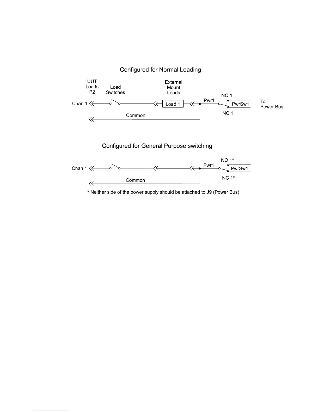
Figure 5-29 Using the 24-Channel Load Card Switches as GP Relays

Table of Contents

Questions and Answers:

Question and Answer IconNeed help?

Do you have a question about the Agilent Technologies E6198B and is the answer not in the manual?

Agilent Technologies E6198B Specifications

General IconGeneral
BrandAgilent Technologies
ModelE6198B
CategoryTest Equipment
LanguageEnglish

Related product manuals