5-30 E6198B Switch/Load Unit User Manual
5 Using Load Cards and Loads
The flyback protection devices should be installed with the
positive side towards the UUT. On each of the 16 channels the
high (+) side should be located as shown in the component
locator diagram, Figure 5-41. MOV (Metal Oxide Varistor), or
back-to-back zener diodes are recommended for flyback voltage
protection.
*
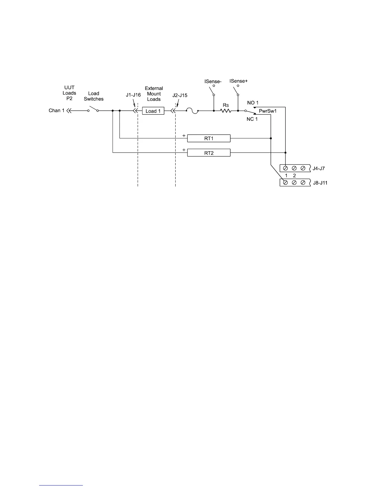
Protection Devices
Zener Diodes, MOVs (Metal-Oxide Varistor) or Transzorbs
®
devices mounted at RTx or RTy (2 required per load - 1 at NC
and 1 at NO) provide current path for the inductive load
flyback. Select the protection device so that it conducts at a
voltage higher than the UUT's internal protection. If the device's
internal protection fails, then the added external protection
conducts to protect the UUT and the load card.
Figure 5-20 16-Channel Load Card - Flyback Circuit Detail
l
* The card was tested using a General Electric GE MOV II, MA series MOV