B-8 E6198B Switch/Load Unit User Manual
B Register Definitions
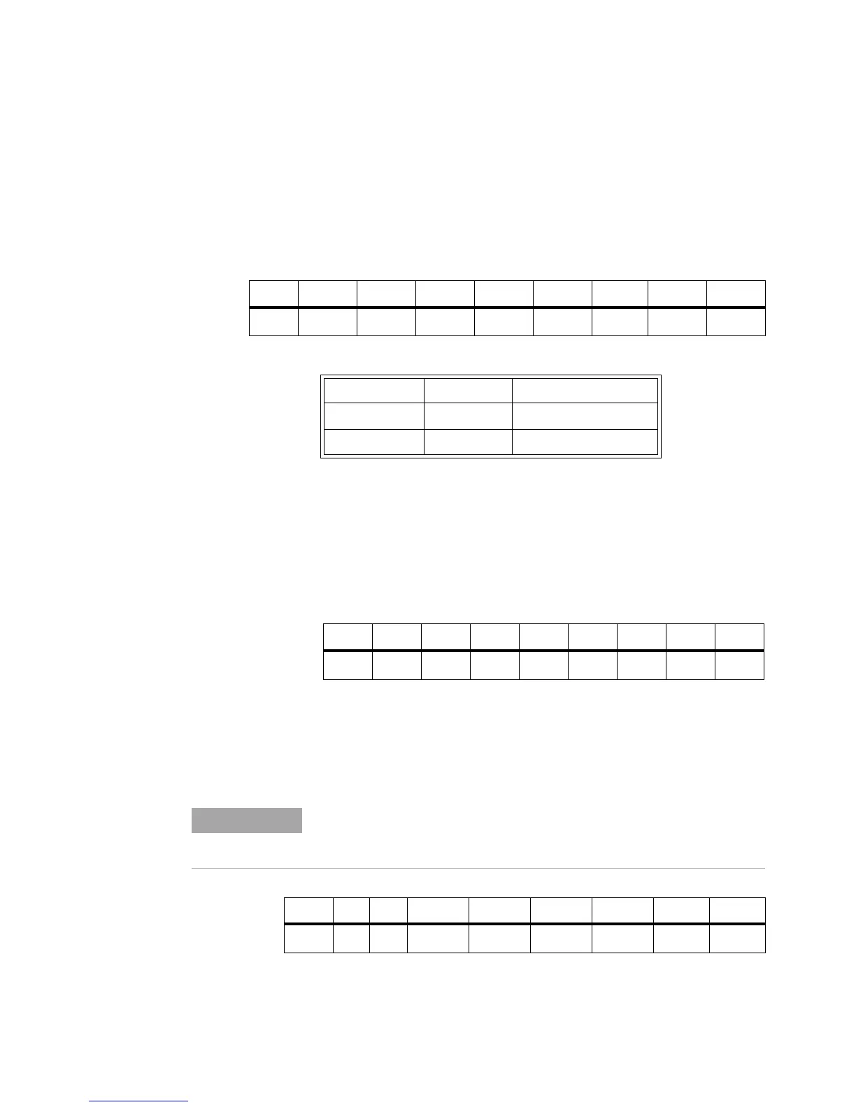
Open Collector Output (W) Base + B
h
The Open Drain Output register controls the state of the
Switch/Load Unit backplane mounted open drain drivers. The
open drain drivers can sink up to 200 mA individual, 150 mA
with all drivers on at once. The drivers have a light pull-up to
Vcc (100 k ohm).
Digital Output (W) Base + C
h
Writing to the Digital Output register sets the output value of
the Spare_DigOut[0]-Spare_DigOut[7] signals present on back
plane connector J104. Spare_DigOut[0]- Spare_DigOut[7]
outputs will directly reflect the contents of this register (1 =
high, 0 = low).
DAC2 Output MSB(W) Base + D
h
Writing to the DAC2 Output register sets the Most Significant
Bit (MSB) of the DAC2 digital input.
Bits76543210
Write
OCout
7
OCout
6
OCout
5
OCout
4
OCout
3
Ocout
2
OCout
1
OCout
0
Table B-5 OCout
x
States
Register State Driver State Nominal Output value
0 off Float to +5 V
1 on Pulled to ground.
Bits76543210
Write
Dout
7
Dout
6
Dout
5
Dout
4
Dout
3
Dout
2
Dout
1
Dout
0
To set the value of the DAC output, always write the MSB first, followed
by the LSB (register offset E
h
). The output of the DAC will not update until
the LSB is written. See “DAC Scaling".
Bits76543210
Write
x xDAC2
13
DAC2
12
DAC2
11
DAC2
10
DAC2
9
DAC2
8

 Loading...


