Using Load Cards and Loads 5
E6198B Switch/Load Unit User Manual 5-69
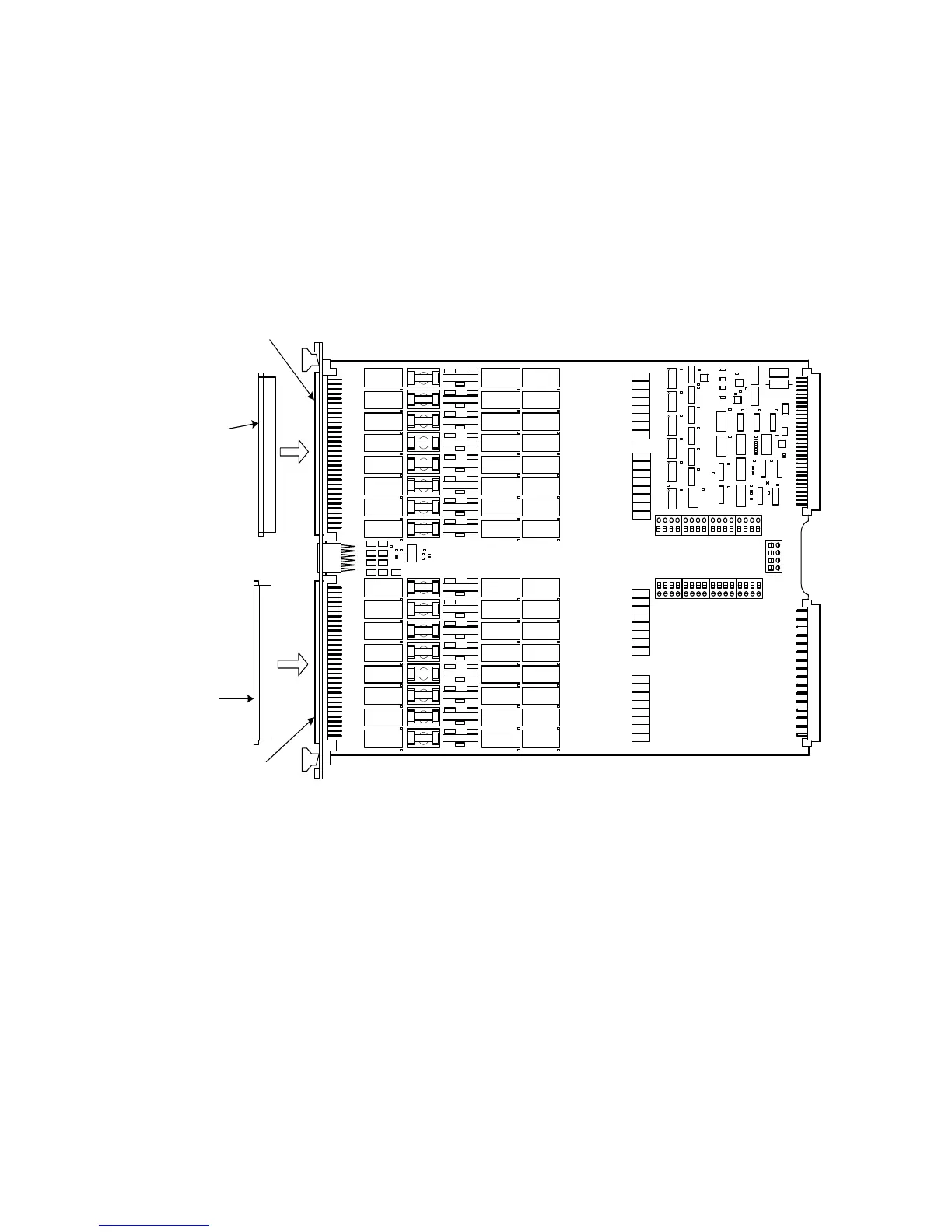
Connecting Loads
Loads are mounted externally and connected to the load card
via wires or cables. The loads are wired to connectors which
mate to the Agilent N9377A’s J1 and J2 connectors,
respectively. Figure 5-48 shows these connectors.
Load Wiring
Loads 1 through 8 connect to the J1 connector and loads 9
through 16 connect to the J2 connector. Each pin is rated for 2A
continuous. The following figures show details to help you
correctly wire loads to the connectors.
• Figure 5-49 shows a load wiring schematic.
• Figure 5-50 shows the connector pin layout.
• Figure 5-51 shows the connector pinouts for J1 and J2.
Figure 5-48 Agilent N9377A Connectors J1/J2 and Mating Connectors J1/J2
P2
P1
K325
K324
K326
K327
K329
K328
K331
K330
K317
K316
K319
K318
K320
K321
K322
K323
J1
Mati ng
Connector
for J1
J2
Mat ing
Connector
for J2