5-74 E6198B Switch/Load Unit User Manual
5 Using Load Cards and Loads
Current Sharing
Each pin in the J1 and J2 connectors is rated for 2 amps, but the
N9377A load card is rated for 7.5 amps. You can accommodate
higher amperage loads by sharing pins on the connector. (Notice
in the wiring schematic, Figure 5-49 that pins A-E in each row of
J1 and J2 are connected together on the PC board.) When
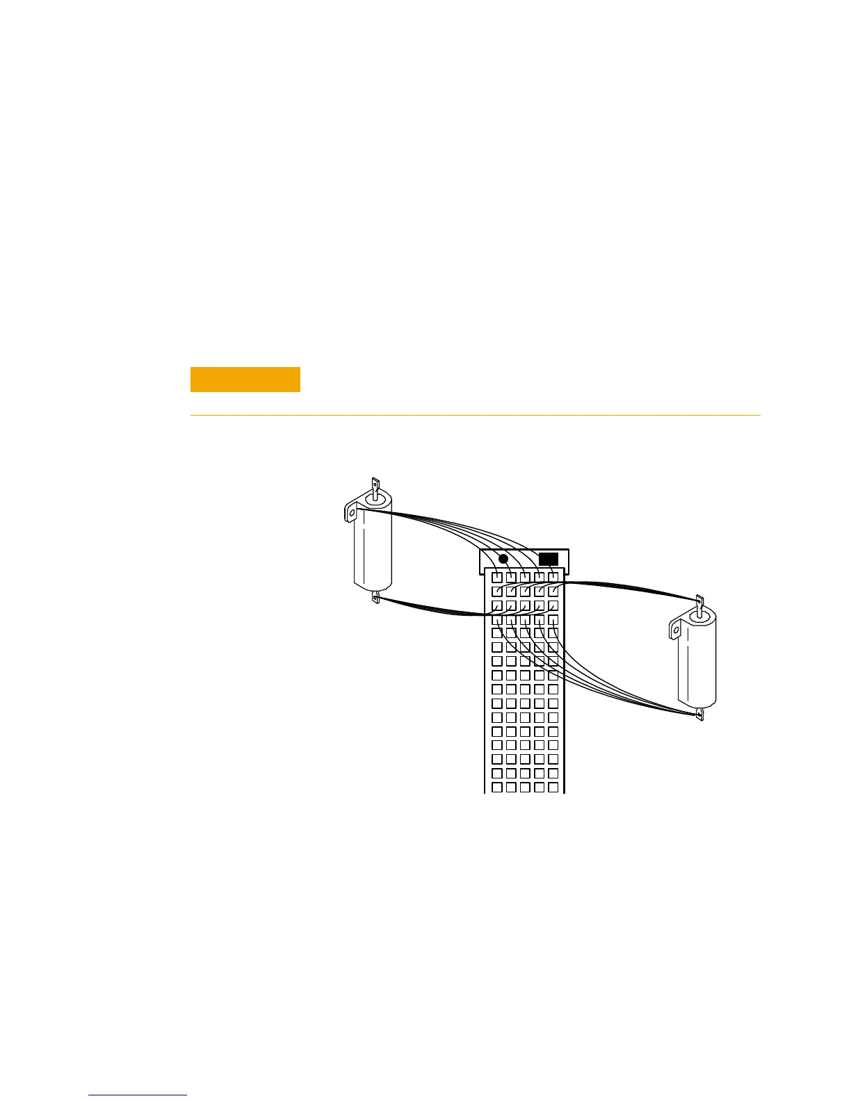
connecting high-current (>2 amp) loads, wire across all five pins
in each row of the connectors (see Figure 5-52). This ensures
current sharing across all pins and prevents premature pin
failure from the excessive current flow.
External Load Mounting Options
As with the E6176A 16-channel load card, you can mount the
loads externally on a metal plate that fits into the SLU slots
adjacent to the load card. For guidelines on mounting loads
externally, see “External Load Mounting Options".
Connecting high-current (>2 amp) loads without wiring across all
five pins in the row can cause premature pin failure.
Figure 5-52 Agilent N9377A Current Sharing Example
J1 Connector
(Wiring Terminal View)
Row 32
Load 1.1
Load 1.2