Home
Agilent Technologies
Test Equipment
E6198B
Agilent Technologies E6198B User Manual
5
of 1
of 1 rating
318 pages
Give review
Manual
Specs
To Next Page
To Next Page
To Previous Page
To Previous Page
Loading...
3-4
E6198B Switch/Load Unit User Manual
3
Switch/Load Unit and Plug-In Card
s
In addition to holding load card
s, pin matrix car
ds and custom
cards, the Switch/Load Un
it also pro
vides the follo
wing
capabilities.
Figure 3-1
Agilent E6198B Standalone Switch/Load Unit Front V
iew
Figure 3-2
Agilent E6198B Standalone Switch/Load Unit Back
View
33
35
Table of Contents
Default Chapter
2
Safety Notices
2
Table of Contents
3
List of Figures
11
List of Tables
15
Declaration of Conformity
17
Legal Information
20
Warranty
20
Technology Licenses
20
Restricted Rights Legend
20
Service and Support
21
Agilent on the Web
21
Agilent by Phone
21
Legal Information
21
Table 1-1. Agilent Sales and Support Contact Numbers
22
Safety and Regulatory Information
24
Safety Information
24
Safety Summary
24
Safety Notice
24
General
24
Environmental Conditions
25
Before Applying Power
25
Table 2-1 Environment Requirements
25
Ground the System
26
Fuses
26
Operator Safety Information
26
Safety Symbols and Regulatory Markings
27
Table 2-2 Safety Symbols and Regulatory Markings
27
2 Safety and Regulatory Information
25
End of Life: Waste Electrical and Electronic Equipment (WEEE) Directive 2002/96/EC
29
3 Switch/Load Unit and Plug-In Cards
32
Switch/Load Unit and Plug-In Cards
32
E6198B Standalone/Integrated Switch/Load Unit Rating
32
Electrical
32
Mechanical
32
Table 3-1 Switch/Load Unit Rating (Electrical)
32
Table 3-2 Switch/Load Unit Rating (Mechanical)
32
2 Safety and Regulatory Information
33
E6198B Standalone Switch/Load Unit Description
33
Switch/Load Unit and Plug-In Cards
33
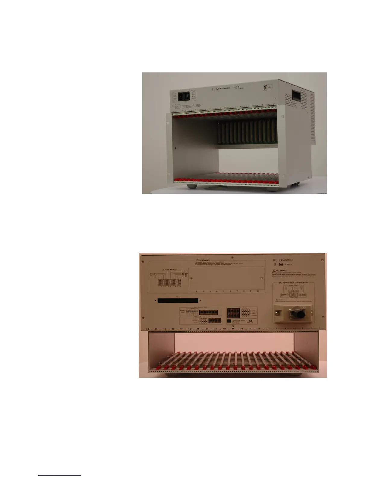
Figure 3-1 Agilent E6198B Standalone Switch/Load Unit Front View
34
Figure 3-2 Agilent E6198B Standalone Switch/Load Unit Back View
34
Digital I/O
35
Digital Input
35
USB Interface
35
5Vdc, +12Vdc, -12Vdc, Spare Power
36
DAC Channels
36
Figure 3-3 Digital Input Example
36
Figure 3-4 Digital Output Example
36
Open Drain Digital Output
36
Current Sense
37
Power Bus Sense
37
Switch/Load Unit Block Diagram
37
Figure 3-5 Switch/Load Unit Block Diagram
38
E6198B Integrated Switch/Load Unit Description
39
Figure 3-6 E6198B Integrated SLU Back View
39
Backplane and Breakout Board Connectors and Leds
40
Figure 3-7. Switch/Load Unit Backplane Connectors
40
Figure 3-8 Switch/Load Unit Breakout Board Connectors (Standalone Only)
41
Backplane Connector Name
42
Backplane J1, J2 and J3 Connectors
42
Table 3-3 Backplane Connectors for E6198B
42
Table 3-4 Backplane Factory Default Connector Settings
42
Breakout Board Connector Name (for E6198B Standalone Option)
43
Backplane Connectors
44
Backplane Leds
45
J102 Pinouts
45
Figure 3-9 Switch/Load Unit J102 Connector Pinouts
46
Figure 3-10 Cable Connector Pinouts
47
Table 3-6 J102 Signal Definitions
48
J1 Pinout
49
J2 Pinout
49
J3 Pinout
49
Table 3-7 Switch/Load Unit J1 Pinout
49
Table 3-8 Switch/Load Unit J2 Pinout
49
Table 3-9 Switch/Load Unit J3 Pinout
49
T1-T14 SLU Logic Power Supply Connector
50
Table 3-10 Power Supply Input for each Jumpers
50
Differentiating E6198B Standalone Option and System Integrated Option
51
Figure 3-11 Switch/Load Unit Rear View (Standalone Option)
51
Figure 3-12 Switch/Load Unit Rear View (System Integrated Option)
52
DC Power Bus Connections
53
Fuse Ratings
53
Table 3-11 Fuses Ratings
53
Configuring the Switch/Load Unit
56
Card Location Recommendations
56
Load Card Types and IDS
58
Figure 4-1 Example of Load/Matrix/Custom Cards Loading Order
58
4 Configuring the Switch/Load Unit
58
Connecting an Additional (Spare) Power Supply
59
Figure 4-2 Component Location/Schematic for User-Installed External Power Supply
59
Figure 4-3 Spare Supply (Input) Connector on SLU Rear (SLU Standalone)
59
Configuring the Power Busses
60
Figure 4-4 Power Bus Connectors J801 and J802
60
Figure 4-5 Example A: Three Separate Supplies on PB1 - PB4
60
Figure 4-6 Example B: Isolated Power Supplies
61
Figure 4-7 DC Power Bus Connector of Standalone SLU
61
Figure 4-8 Conceptional View of Local/Remote Sensing
62
Setting the UUT Power Supply Remote/Local Sense Jumpers
62
Figure 4-10. PB Sense Remote/Local and Frame Select Interface (Integrated SLU)
63
Figure 4-9 PB Sense Remote/Local Interface (Standalone SLU)
63
Configuring the Current-Sense Jumpers
64
Figure 4-11 Isense Bussed/Split Interface (Standalone SLU)
64
Figure 4-12 Isense Bussed/Split Interface (Integrated SLU)
65
Connecting E6198B to the Computer Via USB Interface or Parallel Port
66
Figure 4-13 USB Cable Connections
66
Adding a Second Switch/Load Unit
67
Figure 4-14 Frame Select Interface (Standalone SLU)
67
Load Box Installation
68
Figure 4-15 Load Box Installed
68
Using Load Cards and Loads
69
5 Using Load Cards and Loads
70
Load Card Capabilities
70
Table 5-1 Load Card Capabilities
70
5 Using Load Cards and Loads
72
Loads Overview
72
Figure 5-1 Loads/Sources Conceptual Overview
72
Using the Load Cards
73
Load Card Type and Configuration ID
73
Figure 5-2 Pin Assignments on the Card Configuration Jack
73
Using the Agilent E6175A 8-Channel Load Card
75
Figure 5-3 Agilent E6175A 8-Channel High-Current Load Card Block Diagram
76
Figure 5-4 Agilent E6175A 8-Channel Load Card Layout
77
Selecting a Power Supply Configuration
77
Selecting a Current-Sense Method
78
Figure 5-5 LEM Current Transducer
79
Installing a LEM Current Transducer
79
Figure 5-6 Component Location for Installing LEM Current Transducer Module
80
Figure 5-7 Wiring Options of LEM Model LA25-NP Primary for Various Current Ranges
81
Table 5-2 Components Involved in LEM Module Installation
81
Selecting and Loading Flyback Protection
82
Figure 5-8 8-Channel Load Card Detail - Flyback Protection Circuit
83
Figure 5-9 Agilent E6175A Flyback Protection Polarity
83
Figure 5-10 Typical Agilent E6175A Load Card Flyback Protection Circuit
84
Protection Devices
84
Sample Load Configurations
85
Selecting a Load Fuse
85
Figure 5-11 Agilent E6175A Load Examples
86
Figure 5-12 Bridge Configuration for Channels 7 and 8 on 8-Channel Load Card
87
Setting up a Bridge Configuration
87
Connecting Loads
88
Figure 5-13 Agilent E6175A Load Mounting Area and P1/J1 Connectors
88
Figure 5-14 Agilent E6175A Load Wiring Schematic and P1 Pinouts
89
Load Wiring
89
Current Sharing
90
Figure 5-15 Agilent E6175A Current Sharing Example
90
UUT Connections
91
Figure 5-16 Agilent E6175A 8-Channel High-Current Load Card UUT Connections
92
Front View
92
Using the Agilent E6176A 16-Channel Load Card
93
Figure 5-17 Agilent E6176A 16-Channel High-Current Load Card Block Diagram
94
Figure 5-18 Agilent E6176A 16-Channel Load Card Layout
95
Selecting a Power Supply Configuration
95
Selecting a Current-Sense Resistor Value
96
Selecting a Load Fuse
96
Selecting and Loading Flyback Protection
96
Figure 5-19 16-Channel Load Card - Flyback Device Polarity Orientation
97
Figure 5-20 16-Channel Load Card - Flyback Circuit Detail
98
Protection Devices
98
Figure 5-21 Typical Agilent E6176A Load Card Flyback Protection Circuit
99
Connecting Loads
100
Figure 5-22 Agilent E6176A Connectors J1/J2 and Mating Connectors P1/P2
100
Load Wiring
100
Figure 5-23 Agilent E6176A Load Wiring Schematic and P1/P2 Pinouts
101
Current Sharing
102
Figure 5-24 Agilent E6176A Current Sharing Example
102
External Load Mounting Options
103
Figure 5-25 Example: Load Plate with Loads
104
UUT Connections
104
Figure 5-26 Agilent E6176A P2 Connector Pinouts
105
Using the Agilent E6177A 24-Channel Load Card
106
Figure 5-27. Agilent E6177A 24-Channel Medium-Current Load Card Block
107
Card Layout
108
Figure 5-28 Agilent E6177A 24-Channel Load Card Layout
108
Selecting a Power Supply Configuration
109
Using the Power Switches as General Purpose Relays
109
Connecting Loads
110
Figure 5-29 Using the 24-Channel Load Card Switches as GP Relays
110
Figure 5-30 Agilent E6177A Load Mounting Area and P1/J1 Connectors
111
Figure 5-31 Agilent E6177A Load Wiring Schematic and P1 Pinouts
112
Load Wiring
112
Figure 5-32. Agilent E6177A 24-Channel Medium-Current Load Card UUT
113
UUT Connections
113
Using the Agilent U7177A 24-Channel Load Card
114
Figure 5-33. Agilent U7177A 24-Channel Medium-Current Load Card Block
115
Figure 5-34 the U7177A Layout
116
Selecting a Power Supply Configuration
116
Selecting a Current-Sense Resistor Value
117
Using the Power Switches as General Purpose Relays
117
Connecting Loads
118
Figure 5-35 Using the 24-Channel Load Card Switches as GP Relays
118
Figure 5-36 Agilent U7177A Connector J1 and Mating Connector P1
119
Load Wiring
119
Figure 5-37 Agilent U7177A Load Wiring Schematic and P1 Pinouts
120
Figure 5-38. Agilent U7177A 24-Channel Medium-Current Load Card UUT
121
UUT Connections
121
Using the Agilent E6178B 8-Channel Load Card
122
Figure 5-39 Agilent E6178B 8-Channel Heavy Duty Load Card Block Diagram
123
Figure 5-40 Agilent E6178B 8-Channel Heavy Duty Load Card Layout
124
Selecting a Power Supply Configuration
124
Local / Remote Sensing
125
Selecting a Load Fuse
125
Current Monitor
126
Selecting and Loading Flyback Protection
126
Figure 5-41 Typical Agilent E6178B Load Card Flyback Protection Circuit
127
Protection Devices
127
Load and UUT Connections
128
Figure 5-42 Agilent E6178B Load Card Wiring
129
Using the Agilent N9377A 16-Channel Dual-Load Load Card
130
Figure 5-43 Agilent N9377A 16-Channel Dual-Load Load Card Block Diagram
131
Figure 5-44 N9377A 16-Channel Load Card Layout
132
Selecting a Current-Sense Resistor Value
133
Selecting a Load Fuse
133
Selecting a Power Supply Configuration
133
Figure 5-45 N9377A Load Card - Flyback Locator and Polarity Orientation
134
Selecting and Loading Flyback Protection
134
Figure 5-46 N9377A Load Card - Flyback Circuit Detail
135
Protection Devices
135
Figure 5-47 Typical Agilent N9377A Load Card Flyback Protection Circuit
136
Connecting Loads
137
Figure 5-48 Agilent N9377A Connectors J1/J2 and Mating Connectors J1/J2
137
Load Wiring
137
Figure 5-49 N9377A Load Wiring Schematic
139
Figure 5-50 J1 and J2 Connector Layout
140
Figure 5-51 Agilent N9377A Pinout Table (160-Pin Option)
141
Recommended Connectors
141
Current Sharing
142
External Load Mounting Options
142
Figure 5-52 Agilent N9377A Current Sharing Example
142
UUT Connections
143
Using the Agilent N9378A 24-Channel Low Resistance Load Card
144
Figure 5-53 Agilent N9378 24-Channel Low-Resistance Load Card Block Diagram
145
Figure 5-54 Agilent N9378A 24-Channel Load Card Layout
146
Figure 5-55 Load Circuit Details
147
Selecting a Power Supply Configuration
147
Using the Power Switches as General Purpose Relays
147
Connecting Loads
148
Figure 5-56 Agilent N9378A Load Mounting Area and P1/J1 Connectors
149
Installing and Removing Mezzanine Cards
149
Figure 5-57 Mezzanine Card Pinouts for N9378A 24-Channel Load Card
150
UUT Connections
150
Wiring the Mezzanine Cards
150
Figure 5-58 Agilent N9378A UUT Connector
151
Using the Agilent N9379A 48-Channel High-Density Load Card
152
Figure 5-59 Agilent N9379A 48-Channel High-Density Load Card Block Diagram
153
Card Layout
154
Figure 5-60 Agilent N9379A Layout
154
Figure 5-61 Load Circuit Details
155
Load Circuit Details
155
Selecting a Power Supply Configuration
155
Connecting Loads
156
Figure 5-62 Agilent N9379A Mezzanine Card
156
Using the Power Switches as General Purpose Relays
156
Using the Pin Matrix Cards
159
6 Using the Pin Matrix Cards
160
Using the 32-Pin Matrix Cards
160
Conceptual Overview
160
Features
160
Figure 6-1 Pin Matrix Cards Conceptual Overview
160
Detailed Block Diagram Descriptions
161
Differences between the Cards
161
Features Common to both Cards
161
Figure 6-2 Agilent E8792A Detailed Block Diagram
163
Figure 6-3 Agilent E8793A Detailed Block Diagram
164
Relay Timer
165
Column Disconnect Relay Control
165
Oar
165
Reset
165
Protection Bypass
166
Reset State
166
User Connectors and Pinouts
166
Figure 6-4 Column Disconnect and Protection Bypass Relays
166
J1 Connector Pinouts
167
Figure 6-5 J1 Pinouts--Instrument and Abus Access
168
J1 Instrument Connections
169
Figure 6-6 J1 Example Instrument Connections
169
Figure 6-7 Instrument BNC Cables
170
Figure 6-8 J2 Pinouts--Rear Aux Access
171
P2 Connector Pinouts
172
Figure 6-9 P2 Pinouts--Row, Aux, and UUT Common Main Access
172
Installing in the Switch/Load Unit
173
Figure 6-10. Installed 32-Pin Matrix Cards
173
Using the 64-Pin Matrix Cards
174
Conceptual Overview
174
Features
174
Figure 6-11 Pin Matrix Cards Conceptual Overview
174
Detailed Block Diagram Descriptions
175
Differences between the Cards
175
Features Common to both Cards
175
Figure 6-12 Agilent E8782A Detailed Block Diagram
177
Figure 6-13 Agilent E8783A Detailed Block Diagram
178
Oar
179
Reset
179
Protection Bypass
179
Reset State
180
User Connectors and Pinouts
180
Figure 6-14 Column Disconnect and Bypass Protection Relays
180
J1 Connector Pinouts
181
Figure 6-15 J1 Pinouts--Instrument and Abus Access
181
Figure 6-16 J2 Pinouts--Rear Aux Access for E8782A
183
Figure 6-17 J2 Pinouts--Rear Aux Access for E8783A
184
P2 Connector Pinouts
185
Figure 6-18 P2 Pinouts--Row, Aux, and UUT Common Main Access for E8782A
185
Figure 6-19 P2 Pinouts-Row, Aux, and UUT Common Main Access for E8783A
186
Installing in the Switch/Load Unit
187
Figure 6-20 Installed 32-Pin Matrix Cards
187
Using the Custom Card
190
General-Purpose Breadboard
190
TS-5430 Series I Emulation
190
Digital I/O
190
Figure 7-1 Custom Card Features
191
7 Using the Custom Card
191
Connector Breakouts
192
J2 Connector Breakouts
192
Figure 7-2 J2 Configuration Lines Pinouts
192
J3/J4 Connector Breakouts (DAC)
193
Figure 7-3 J3/J4 Breakouts for Agilent E1418 DAC
193
J3 or J4 Connector Breakouts (Event Detector)
194
Figure 7-4 J3 or J4 Connector Breakouts for Agilent E6174 Event Detector
194
J5 and J6 Connector Breakouts (32-Pin Matrix Cards)
195
Figure 7-5 J5 and J6 Breakouts (32-Pin Matrix Cards)
195
E8794A Components and Schematics
196
Figure 7-6 E8794A Layout
196
Figure 7-7 E8794A Component Locator
197
Figure 7-8 E8794A Schematic
198
Figure 7-9 Status and Control Interface
199
A Switch/Load Unit and Card Specifications
202
Agilent E6198B Switch/Load Unit Specifications
202
Agilent E6175A 8-Channel High-Current Load Card Specifications
203
Agilent E6176A 16-Channel High-Current Load Card Specifications
204
Agilent E6177A 24-Channel Medium-Current Load Card Specifications
205
Agilent U7177A 24-Channel Medium-Current Load Card Specifications
206
Agilent E6178B 8-Channel Heavy Duty Load Card Specifications
207
Agilent N9377A 16-Channel Dual-Load Load Card Specifications
208
Agilent N9378A 24-Channel Low-Resistance Load Card Specifications
209
Agilent N9379A 48-Channel High-Density Load Card Specifications
210
Agilent E8792A and E8793A Specifications
211
Instrument Multiplexer (Agilent E8792A Only
211
General Specifications (Agilent E8792A and E8793A
211
Relay Characteristics (Agilent E8792A and E8793A
212
Agilent E8782A and E8783A Specifications
213
Instrument Multiplexer (Agilent E8782A Only
213
General Specifications (Agilent E8782A and E8783A
213
Relay Characteristics (Agilent E8782A and E8783A
214
Relay Life
214
End-Of-Life Detection
214
Replacement Strategy
215
Address Space
217
Register Definitions
217
B Register Definitions
218
Table B-1 Standard Registers
218
Table B-2 Standard Registers
218
Base Address
219
Switch/Load Unit Register Definitions
220
Table B-3 Switch/Load Unit Registers
220
Card Type (R)Base + 0
221
Card Configuration (R) Base + 1
221
Status Register (R) Base + 2
221
Fixture ID (R) Base + 3
222
Digital Input (R) Base + 4
222
DAC1 Output MSB (W) Base + 8
222
DAC1 Output LSB (W) Base + 9
222
DAC Scaling
223
Control Register (W) Base + a H
223
Table B-4 DAC Scaling Examples
223
Open Collector Output (W) Base + B H
224
Digital Output (W) Base + C H
224
DAC2 Output MSB(W) Base + D H
224
Table B-5. Ocout
224
DAC2 Output LSB (W) Base + E H
225
Table B-6 Summary of Load Card Register Definitions
226
Agilent E6175A 8-Channel High-Current Load Card
227
Agilent E6176A 16-Channel High-Current Load Card
231
Agilent E6177A 24-Channel Medium-Current Load Card
235
Card Configuration (R) Base + 1 H
239
Agilent U7177A 24-Channel Medium-Current Load Card with Current Sense
239
Agilent E6178B 8-Channel 30 Amp Load Card Register Definitions
244
Agilent N9377A 16-Channel Dual-Load Load Card
246
Figure B-10 Relay Controlled by Registers Base+03H-Base+09H
246
Agilent N9378A 24-Channel Low-Resistance Load Card
251
Figure B-11 Mezzanine Card Layout
254
Agilent N9379A 48-Channel High-Density Load Card
262
Figure B-12 Mezzanine Card Layout
264
B Register Definitions
246
Pin Matrix Card Register Definition
273
Agilent E8792A and E8793A Pin Card Register Definitions
273
Agilent E8782A 24-Instrument, 40-Measurement Matrix Card
281
Agilent E8783A 64-Pin Matrix Card
290
Agilent E8794A Custom Card Register Definitions
299
Repair Information
301
Support Strategy
302
Locating Load Card Components
302
Agilent E6175A 8-Channel High-Current Card
302
100 C Repair Information
303
Figure C-1. Agilent E6175A Component Locator (Rear View
303
Agilent E6176A 16-Channel High-Current Card
304
Figure C-2. Agilent E6176A 16-Channel Load Card Component Locator (Rear View
304
100 C Repair Information
305
Other Load Cards
305
32-Pin Matrix Modules
305
Table C-1 Measurement Matrix Relays
305
Table C-2 Instrument Matrix Relays
307
Table C-3 Bypass and Disconnect Relays
307
Table C-4 Miscellaneous Relays
307
64-Pin Matrix Modules
308
Table C-5 Measurement Matrix Relays for E8782A
308
Table C-6 Measurement Matrix Relays for E8783A
310
Table C-7 Bypass and Disconnect Relays for E8782A and E8783A
312
Glossary of Terms
313
5
Based on 1 rating
Ask a question
Give review
Questions and Answers:
Need help?
Do you have a question about the Agilent Technologies E6198B and is the answer not in the manual?
Ask a question
Agilent Technologies E6198B Specifications
General
Brand
Agilent Technologies
Model
E6198B
Category
Test Equipment
Language
English
Related product manuals
Agilent Technologies E5515C
165 pages
Agilent Technologies E7495A RF
15 pages
E4406A VSA Series
420 pages
Agilent Technologies 3070
116 pages
Agilent Technologies U1602B
227 pages
Agilent Technologies 54621A
276 pages
Agilent Technologies HP 83711B
251 pages
7000B Series
432 pages
auroraSonata
336 pages
93000 SOC Series
632 pages
Medalist i3070 5i Series
181 pages
InfiniiVision 5000 Series
428 pages