7-6 E6198B Switch/Load Unit User Manual
7 Using the Custom Card
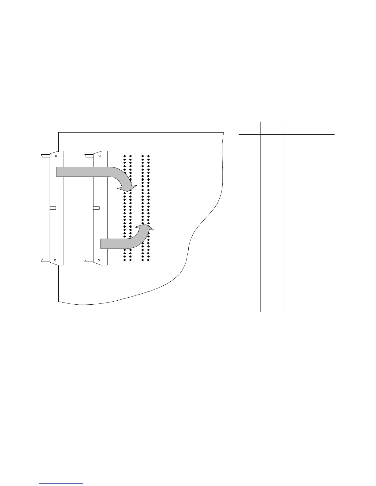
J3 or J4 Connector Breakouts (Event Detector)
The Event Detector can be cabled to either J3 or J4. Figure 7-4
shows the J3 or J4 connector breakouts. Connections are made
to either J3 or J4 to the Agilent E6174 Event Detector.
Figure 7-4 J3 or J4 Connector Breakouts for Agilent E6174 Event Detector
Note: Event Detector can be connected to J3 (left breakout connections) or J4 (right
breakout connections.
Pin
NumberSignal
Pin
NumberSignal
64
62
60
58
56
54
52
50
48
46
44
42
40
38
36
34
32
30
28
26
24
22
20
18
16
14
12
10
8
6
4
2
63
61
59
57
55
53
51
49
47
45
43
41
39
37
35
33
31
29
27
25
23
21
19
17
15
13
11
9
7
5
3
1
CH31
CH30
CH29
CH28
CH27
CH26
CH25
CH24
CH23
CH22
CH21
CH20
CH19
CH18
CH17
CH16
CH15
CH14
CH13
CH12
CH11
CH10
CH9
CH8
CH7
CH6
CH5
CH4
CH3
CH2
CH1
CH0
Gnd
Gnd
Gnd
Gnd
Gnd
Gnd
Gnd
Gnd
Gnd
Gnd
Gnd
Gnd
Gnd
Gnd
Gnd
Gnd
Gnd
Gnd
Gnd
Gnd
Gnd
Gnd
Gnd
Gnd
Gnd
Gnd
Gnd
Gnd
Gnd
Gnd
Gnd
Gnd
J4J3
1122
64 64
J3 Breakouts
J4 Breakouts

 Loading...


