5-82 E6198B Switch/Load Unit User Manual
5 Using Load Cards and Loads
Wiring the Mezzanine Cards
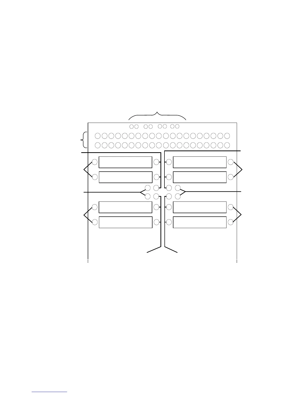
Figure 5-57 shows a detailed view of the top half of a mezzanine
card. The physical layout of the mezzanine card is identical for
the N9378A (24-channel) and the N9379A (48-channel) load
cards. However, the internal wiring of the N9378A card uses the
mezzanine pin arrangements differently.
UUT Connections
When configured as part of a standard Agilent system, P2 of the
load card is typically connected via cables to a mass
interconnect panel. User connections to the UUT are then made
from the mass interconnect panel. Refer to the appropriate
mass interconnect wiring guide for connection details.
You can also make connections directly to P2. Figure 5-58 is a
P2 connector pinout showing the details.
Figure 5-57 Mezzanine Card Pinouts for N9378A 24-Channel Load Card
Mezzanine card IDs
Loadx.4 Load(x+1).4
Load(x+1).3Loadx.3
Loadx.2 Load(x+1).2
Load(x+1).1Loadx.1
1
2
3
4
MEZZ ID
J14
J12
J11
Pwrx
Pwr(x+1)
J15
Comx
Com(x+1)
Comx
Com(x+1)
Chanx
Chanx
Chan(x+1)
Chan(x+1)
Connections
to load card
x = channel number 1, 3, 5, 13, 15, or 17