Using Load Cards and Loads 5
E6198B Switch/Load Unit User Manual 5-11
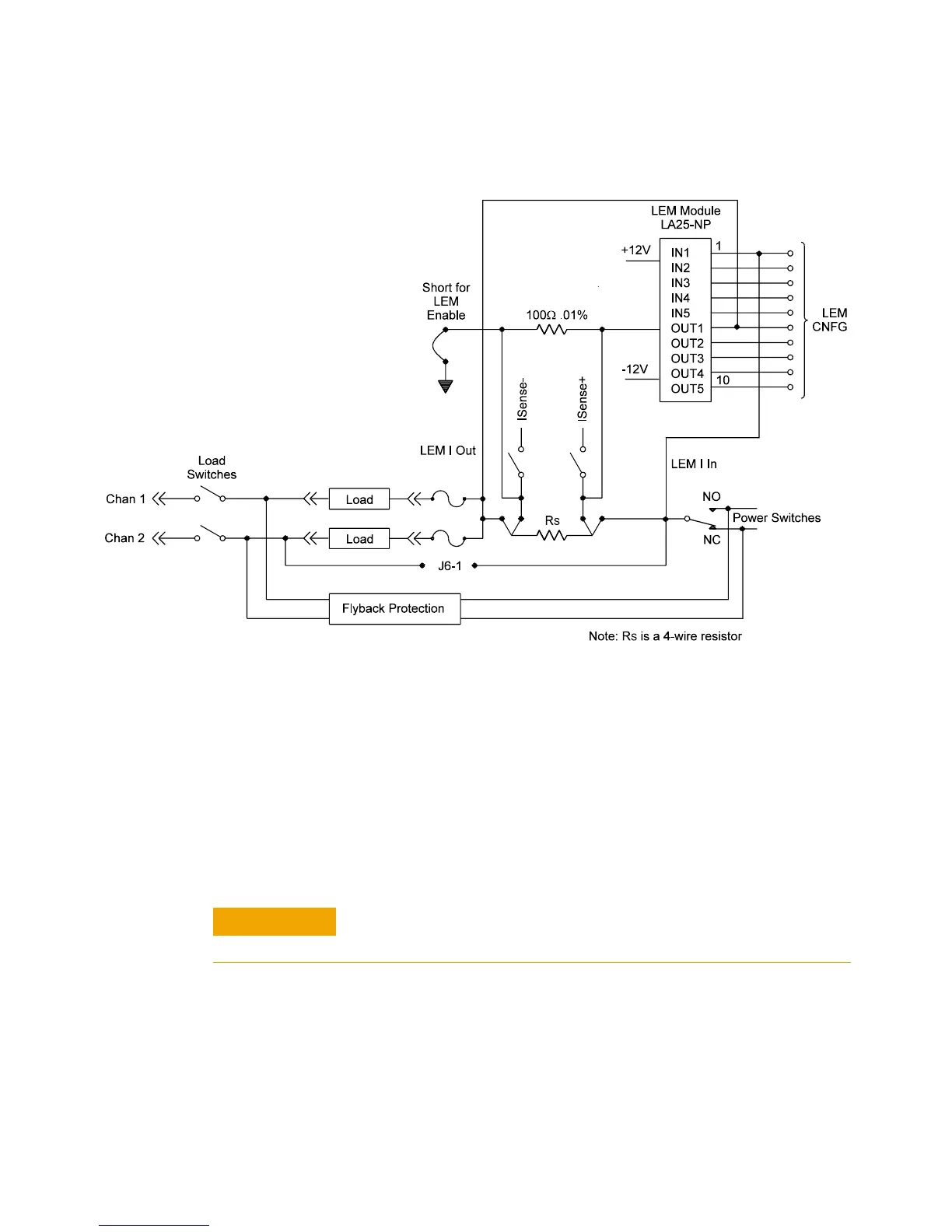
Installing a LEM Current Transducer
Figure 5-6 shows the component location of the current-sense
section of the first two channels on the load card. The location
of the components listed in Table 5-2 are silk-screened on the
load card's printed circuit board. Installing a current transducer
involves both elements of a channel pair. For example, if the
LEM module were to be installed across channels 1-2:
1 Remove the 0.05Ω current-sense resistor (R1).
2 Install the LEM module.
3 Install the measuring resistor, R2 (preferably a 100Ω, 0.1%
resistor).
4 Install the shorting jumper from R2 to ground, TP41 to
TP42.
Figure 5-5 LEM Current Transducer
The current-sense resistor must be removed from the
Agilent E6175A PC board.