Using Load Cards and Loads 5
E6198B Switch/Load Unit User Manual 5-67
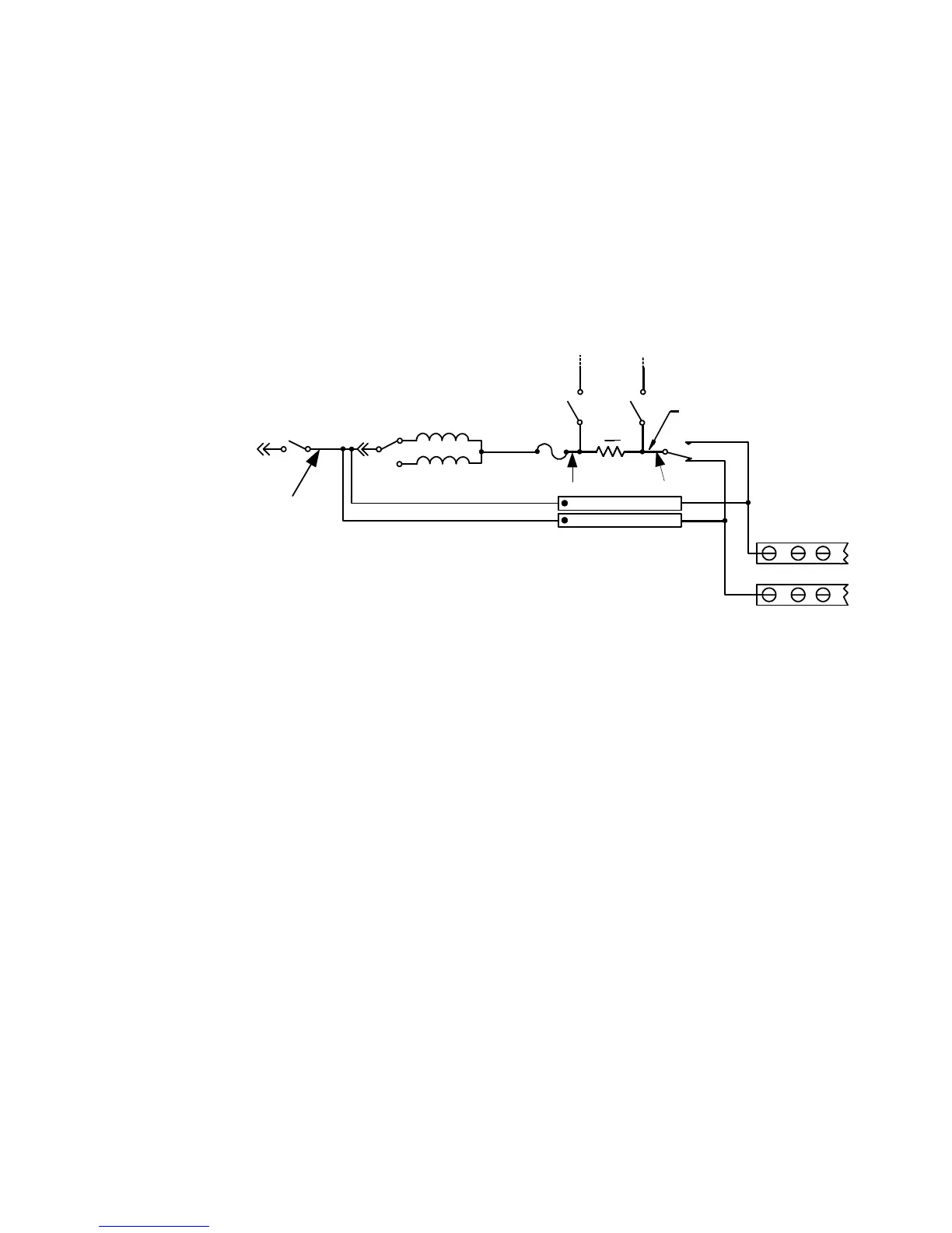
In Figure 5-46, Channel 1 has two input lines connected to the
input Form C switch. RT502 connects input line J4-J7, and
RT501 connects alternate input line J8-J11, to the output of
Load1. When a voltage spike occurs on the UUT that exceeds the
rating on the flyback device, the device clamps the surge voltage
to the device’s predetermined value. The flyback protection is
installed similarly on each input line.
Install the flyback protection devices with the positive or
negative side towards the UUT as appropriate for your
application. On each of the 16 channels, note the location of the
polarization dot as shown in the flyback component locator
diagram, Figure 5-45. MOV (Metal Oxide Varistor), or
back-to-back zener diodes are recommended for flyback voltage
protection.
Protection Devices
Zener Diodes, MOVs (Metal-Oxide Varistor) or Transzorbs
®
devices mounted at RTx or RTy (2 required per load - 1 at NC
and 1 at NO) provide current path for the inductive load
flyback. Select the protection device so that it conducts at a
voltage higher than the UUT's internal protection. If the device's
internal protection fails, then the added external protection
conducts to protect the UUT and the load card.
Figure 5-46 N9377A Load Card - Flyback Circuit Detail
Load
switch
Chan1
PB1
PwrSw1
NO1
R
S
NC1
LdSense+1
LdSense-1
1Pwr
Load1
Load1.1
Load1.2
ISense
-
ISense
+
J8-J11
J4-J7
2
1
RT501
RT502
External
mount
loads
UUT
loads
P2

 Loading...


