3-18 E6198B Switch/Load Unit User Manual
3 Switch/Load Unit and Plug-In Cards
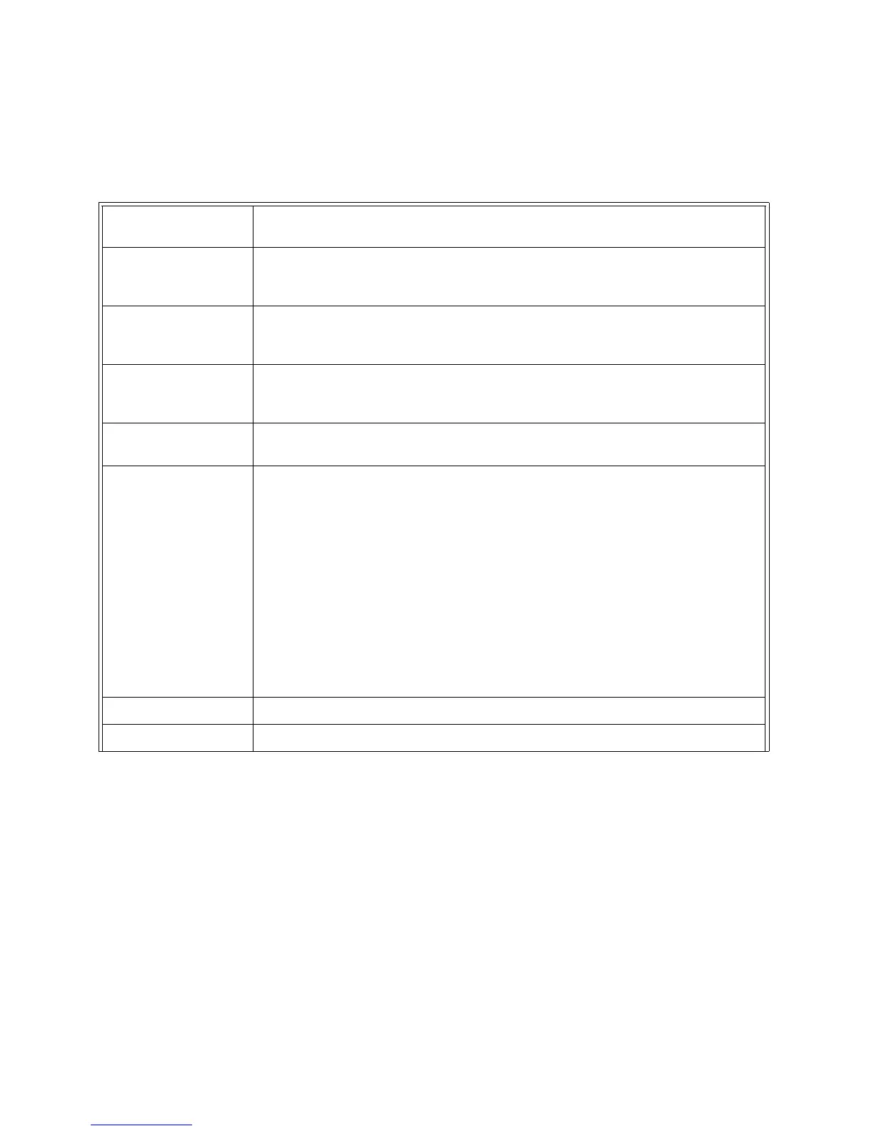
Tab le 3- 6 J102 Signal Definitions
+12Vdc, -12Vdc Supply +12V and -12V from the Switch/Load Unit Power Supply. The +12V supply can deliver
2.5A, the -12V supply can deliver 800mA.
Spare Supply Connection for a user installed power supply not included in the standard system. Refer
to Connecting an Auxiliary Power Supply in the Switch/Load Unit User’s Manual for
details.
DAC1
DAC2
The Switch/Load Unit provides two 14-bit channels of DAC which supply ±16 volts at 10
mA each.
Digital In 0 - 7
Open Drain Out 0 - 7
Spare_DigOut
The Switch/Load Unit provides 8-bits of digital input, 8-bits of open drain digital output,
and 8-bits of TTL-level digital output (Spare_DigOut). There is no handshaking
capability.
Fixture ID (0 - 7) The Fixture ID lets you configure a unique ID for each mass interconnect fixture and
read it back. ID sent as TTL level bits.
Isense+ (1 - 4)
Isense- (1 - 4)
These lines connect to the current sense bus on the Switch/Load Unit backplane. These
lines are used for sensing current on a selected load card channel. The 8-channel and
16-channel load cards are designed to connect to the current sense bus. Each load card
channel’s current sense lines are multiplexed so that on each card only one channel at a
time can be connected to the current sense bus. The current sense lines and the slots
they connect to are:
Isense lines (1) connect to Switch/Load Unit slots 1 - 5.
Isense lines (2) connect to Switch/Load Unit slots 6 - 10.
Isense lines (3) connect to Switch/Load Unit slots 11 - 15.
Isense lines (4) connect to Switch/Load Unit slots 16 - 21.
Two or more sets of the above lines can be bussed together select from toggle switches.
Refer to page 12 for details.
Power Bus Sense 1 - 4 The remote sense lines for the power supplies connected to power buses 1 - 4.
Gnd Chassis ground of the Switch/Load Unit.