3-10 E6198B Switch/Load Unit User Manual
3 Switch/Load Unit and Plug-In Cards
Backplane And Breakout Board Connectors and LEDs
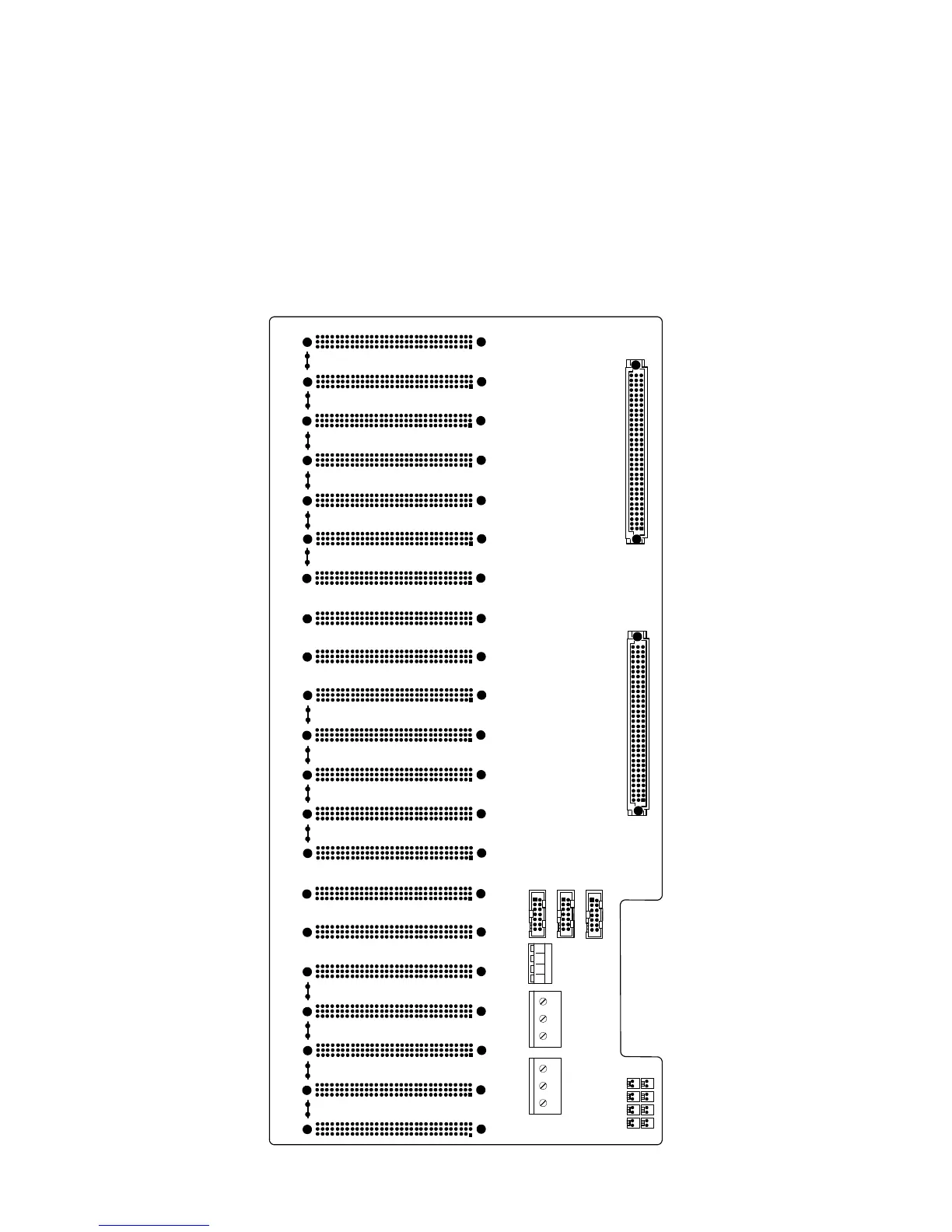
Figure 3-7 shows the locations of the various backplane
connectors and LEDs. These components are described on the
following pages. See Table 3-3 for more detail.
Figure 3-7 Switch/Load Unit Backplane Connectors (USB port adaptor board Not Shown)
BACKPLANE SLU
T4 T8 T9 T1 T5 T10 T11 T2 T6 T12 T13 T3 T7 T14
J102
J101
J1
J3
J2
J803
J801
J802
1
2
14
13
1
214
13
1
2
14
13
1
3
94
96
1
3
94
96
J201
J202J203
J204
J205
J206J207
J208J209
J210J211
J212
J213
J214J215
J216
J217
J218J219
J220
J221
J104
J111 J110
J109
J106 J107
J105 J108