4-14 E6198B Switch/Load Unit User Manual
4 Configuring the Switch/Load Unit
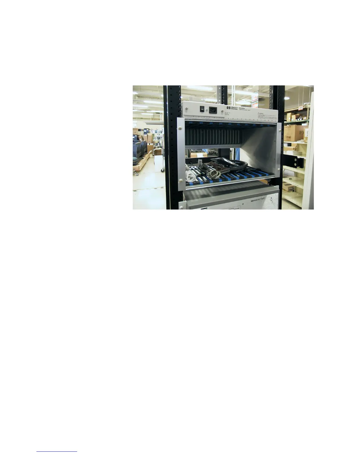
Load Box Installation
Figure 4-15 Load Box installed
• Install 4 tinnermans (0590-0804) at the proper locations on
the back of the rack.
• From the back of the rack, position the load box onto the
rails and secure to the rack using 4 spacers (0380-0317) and
4 dress screws (0570-1272).
• Spacers are only required for the first loadbox (to clear the
door latch).
• Check the build list for the number of load boxes (E6198B)
required. If a second load box (Option E6198B-FG) is
required, another set of rails will need to be installed. Allow
space for the first load box and 1 EIA space for venting
between the two load boxes.
• Secure the second loadbox (if required) with 4 dress screws
(E9900-06001).