4-4 E6198B Switch/Load Unit User Manual
4 Configuring the Switch/Load Unit
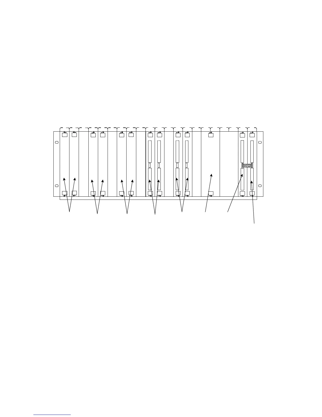
For example, Figure 4-1 shows the standard locations for matrix
and load cards for a system which contains three matrix cards,
a custom card, two 24 channel, four 16 channel, one 8 channel,
and one 8 channel heavy duty load card. If using this
configuration, be sure to leave the slots open between the cards,
as shown in the figure.
Load Card Types and IDS
Each card is assigned a different type and has a 10-pin
connector that lets you assign a unique binary code ID number
to each card. See“Load Card Type and Configuration ID" for
more information.
Figure 4-1 Example of Load/Matrix/Custom Cards Loading Order
Slot:
E8792A 32-Pin
Matrix and
Instrument
Multiplexer
Card
E6175A
8-Channel
Agilent E6176A
16-Channel
Load Cards
N9379A
48-Channel
Switch/Load Unit Slot Front View
Agilent E8794A
Custom Card
Empty
E6177A
24-Channel
Empty
N9378A
24-Channel
Empty
Empty
Empty
N9378A
24-Channel
Empty
1 2 3
4 5 6
7 8 9
10
11 12
13
14 15
16
17 18 19
20 21